M-19 Belly
Constructing the belly
Revised and edited January 13, 2008
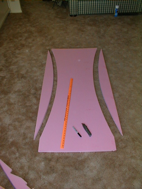
Here's a way to save a step in the construction. Measure and cut the piece for the belly panel, but save the two cutout pieces. It turns out that they are exactly the right size and shape for the two belly ribs, if you measure and cut them properly. The plans say to cut out the ribs, glue them to the underside of the cabin, then glue the belly panel over them... followed by shaping by using a saw held at about a 30 degree angle. That's fine, but it turned out (in my case) that the cutout parts were almost exactly the same size and shape as the belly ribs, so now I have 2 sets. Save yourself some time and effort by doing it this way. Only additional step (after cutting out the pieces as shown) is to bevel the cuts on the belly panel at about a 30 degree angle if you want, but it all gets sanded to shape later anyway, so a square cut is OK as-is.
 Another view of how I cut my pieces.
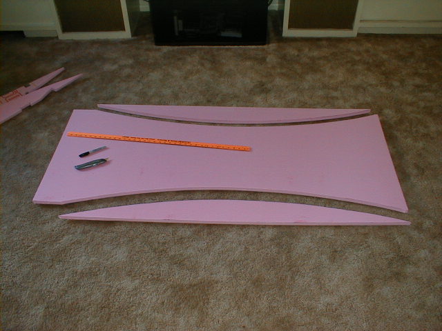
 These are my belly ribs as they would fit in final location. Not yet glued in place, but fitted and smoothed. I made mine as simple, symmetrical curves rather than slightly "humped" at the forward end, as Marvin has his. I also changed the shape of the aileron cable cutouts from oval to "triangular" to ensure cable clearance and also to make it easier to get to the control stick connections. I also had to notch my ribs to clear the bottom corner of the seat and the additional floor brace I had to install since I cut a hole in the floor.
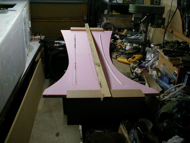
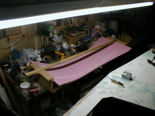 Then I changed my mind about how I'd build the belly ;o) Here's a jig I made to hold the belly panel in a curved shape while I glass the inside of it. I'm eliminating the two belly ribs altogether and replacing them with reinforcing ridges along the inside of the belly, and glassing the inside to add strength and stiffness (and to provide more room and easier access inside the belly). I used two leftover triangular strips of foam to create the reinforcing runners, and stuck them on with hot glue. Great tool, the hot glue gun! I used a leftover piece of foam under the belly panel to make the deepest part of the curve move forward, where it will occur directly below the control stick. That point is where the centerline (marked on the inside of the panel with a Sharpie) intersects the other black line.
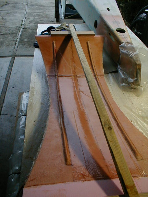
 Another view of the jig. The wood piece across the top applies tension to the ends, but is removable to allow me to load and unload the panel from the jig.
 Here's the finished, glassed panel. The two side pieces will be added after temporarily tacking this section in place (hot glue again!) and fitting/rounding/tacking the side pieces in place. Then I'll remove it from the airplane and complete the glassing of the inside of the belly. If I remember before assembly, it will get a coat of white primer to make inspection inside the belly easier.
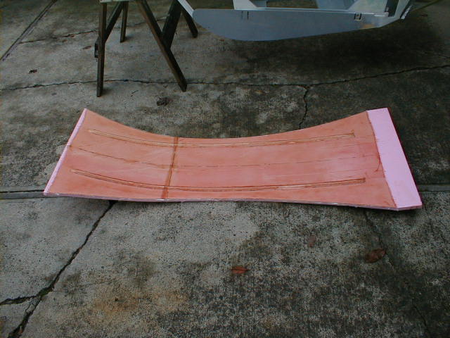 Another view of the finished panel. The jig held it nicely, and the cured fiberglass holds it in shape.
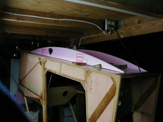
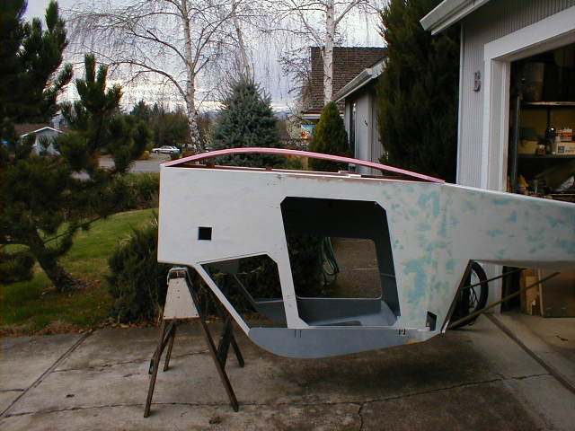 Here's the panel temporarily in place on the airplane. The aft edge of the panel gets sanded to fit flat along the underside of the plane. Actually, the aft edge will move forward an inch or two before I tack it in place, to make the panel bow a bit more to provide the required clearance for the end of the control stick.
Click to return to Oscar Zuniga's M-19 homepage