Cabin Construction III
CABIN CONSTRUCTION - III
Reorganized January 13, 2008
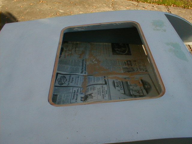
I finally got around to rabbeting the opening for the "skylight" in the cabin roof. The router does a quick, neat job rabbeting in a recess for the 1/16" polycarbonate. I've got to have a view overhead so those ultralights can't sneak up on me from above ;o)
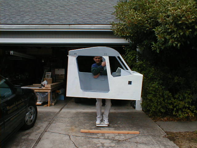 Well, here I am holding the essentially completed cabin assembly on the ol' bathroom scales. It weighs 54 lbs. and I weighed 143 lbs. back when this picture was taken (2000). There are no metal fittings on the cabin, no panel or controls, no fittings... just wood, foam, fiberglass, filler, and primer. No idea if it's heavy or light; we won't know till I finish the airplane and see how it comes in relative to the prototype.
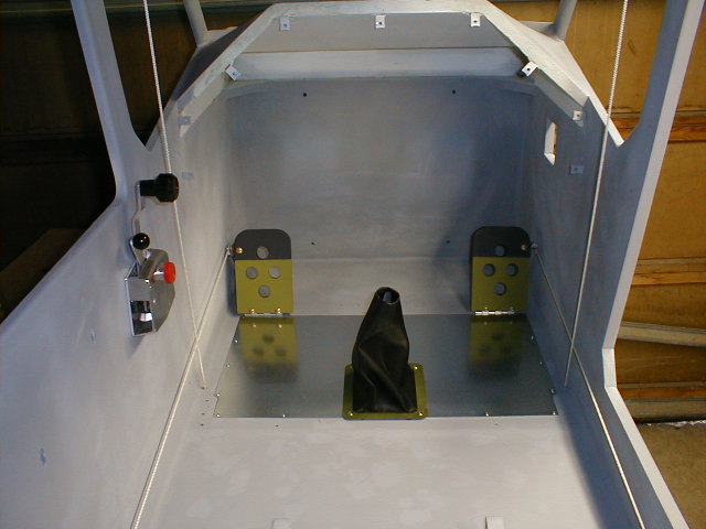 Here's a shot of the interior of the cabin with the rudder pedals, throttle quadrant, floor scuff plate, and control stick boot temporarily installed. Still in primer and still rough, but getting there.
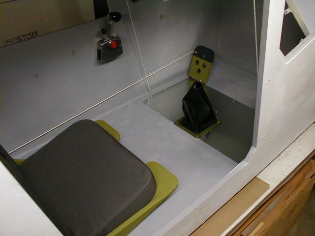 Same view, but with the seat added. Yes, I did get in and sit there a while. No, I didn't make airplane noises (nobody heard me, anyway) ;o)
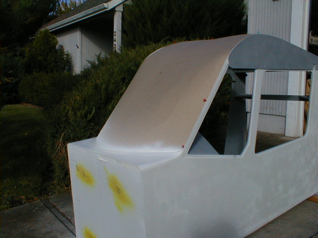 This is the cardboard windshield template I made up. It fits pretty well, but still needs a bit of tweaking. As you can see, I wrapped my windshield up beyond where Marvin's is, to the forward edge of the through-spar, to give me additional upward visibility. You can also see how I changed the lines of the side windows and top deck inside the cabin. As Yakov Smirnoff says, "I love this country!"- you can make changes any way you like!
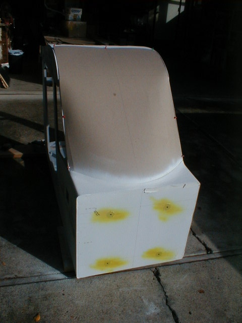 Another shot of the windshield template and top deck.
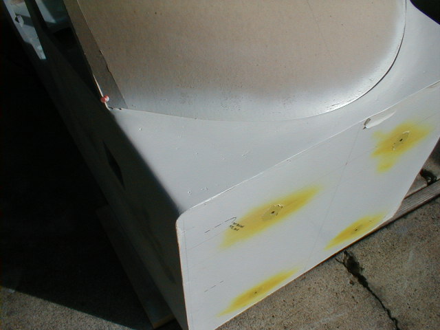 Close-up view of the top deck, showing the usual pinholes, voids, and rough spots that result after the second session of filling/sanding/priming. This will require one or two more sessions until it's satisfactorily smooth. Sigh.
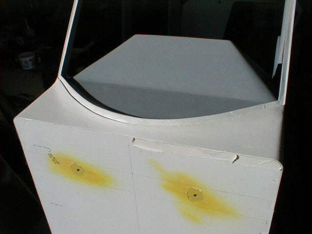 Another shot of the top deck and windshield framing. Again, it's different from Marvin's because I was looking for some slightly different lines.
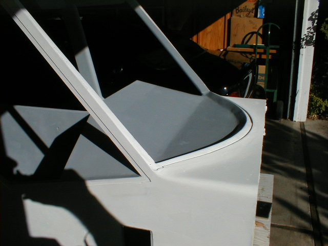 Another angle of the same thing.
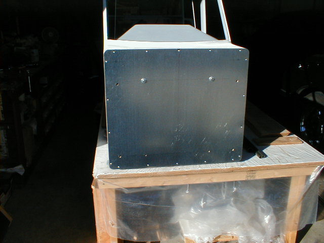 While making a jig for building up the engine mount I made a "fake" firewall using scrap wood, covered it with some sheet metal (duct material), and made all the mounting holes in the correct spots (engine mount holes are the 3/8" ones at the outboard edges; firewall-to-cabin mount holes are the four 5/16" ones of which two have temporary bolts in them). Here I've put the "fake" firewall up to the "real" one to make sure the outlines and mounting holes match. They do. I also mounted the sheet metal to the "fake" firewall using the same screw mount points that I'll be using for the real firewall. These points will have small aluminum angle clips for mounting the cowling to the firewall (I'm using Southco quarter-turn fasteners). The cowling part line has to be right at the center of the heads/valve covers.
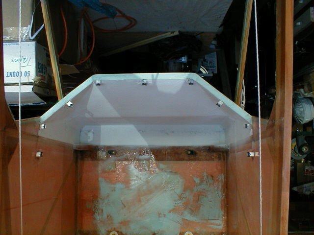 Here's a closer shot of the clips I made for mounting the instrument panel, instead of fiberglass "flanges" as called for in the plans. I simply cut some clips out of light alum. angle, drilled, installed tinnerman j-nuts, and floxed them in place (mounted to the instrument panel, to line everything up). I need to do more finish work here inside the top cowl. FWIW- this picture was actually taken with the cabin on its back, then flipped. That's why things in the background are upside down ;o
If you're not building yet,.........................why not?
Return to My Flying Squirrel Home Page