M-19 Tail
Empennage Construction
revised October 19, 2000

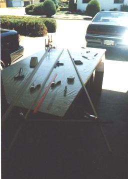
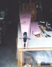
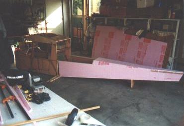
This is what a clean building table looks like! Freshly recovered with plastic film, engine neatly tucked away underneath and plastic wrapped, and longeron material ready to measure and cut. See a problem here? The empennage is over 9'-4" long, but the table is only 8 ft. and Jay won't even _think_ of letting me use any of her half of the garage (see the dividing strip just to the right of my table?) %^( But it's OK; I'll make it work.
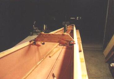
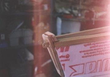
 See; I told you I'd make it work. Several things going on here; at the far edge of the table you can see clamps holding the "doublers" that go on the ends of the top longerons, where the horizontal stabilizers mount to with hinges for folding. The manual sequence says to cut these into the foam sides later, but it seemed easier to me to glue them on before the foam. In the center of the picture you might barely see a stretched string on the centerline of the lower longerons, from which I'm establishing the points where things go, like the spring plate and the tapers on the ends of the longerons. I have a stick clamped to the forward ends, marked with the exact cabin width at the insertion point, holding them apart as they will go when I join them to the cabin. Spent a long time making sure everything was square before I cut the taper/scarf cuts on them.
 OK; here the foam is being glued to the upper and lower longerons to form the two sides of the empennage. I cut them both out exactly alike, then stacked them to align everything and glue them together as a sandwich (with plastic film between them any place I thought they might ooze together). Sandbags and clamps to keep pressure on. Again, everything was checked, re-checked, and checked again to make sure it was square and symmetrical. "Measure twice, cut once".
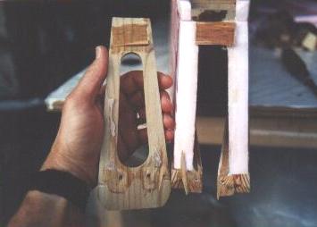
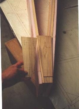 Here are the tailplate (left) and spring plate (right), both cut out of solid cherry wood, planed to proper thickness. Spring plate is just sitting on top of lower longerons, not yet glued. Notch is for the tailspring bracket. The tailplate is cut to rough dimension but pencil marks (you can see the pencil marks, right?) show where center cutout and top radius edges will be, plus elevator bracket footprint. Yep, you guessed it... I measured everything a couple of times before I was satisfied with the angles.
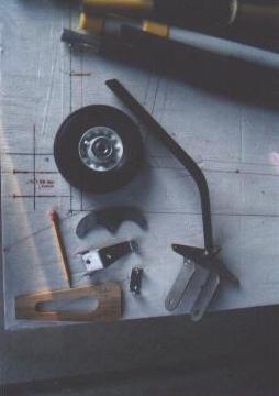 Here are the parts involved in the tailwheel. Pencil is pointing to the tailplate (I made mine of cherry rather than plywood, just because it was on hand); my "experimental" 6" semi-pneumatic tailwheel with grease fitting on the bearings; tailwheel bracket fabricated of stainless steel mounted on the Aircraft Spruce tailspring; center are the elevator horn, tailspring bracket, and elevator horn bracket, all in bead-blasted condition.
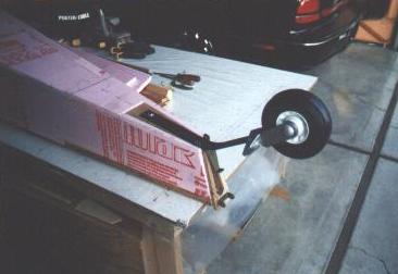
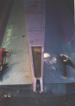
 Here are the pieces, assembled temporarily to see how they look. Tailplate has been glued to the end of the empennage, elevator horn bracket glued and screwed to the ends of the top longerons through the tailplate. Opening in the tailplate is where the elevator control cable comes through. Hmmm... something doesn't look quite square.
 Looking more closely, something is definitely not square with the world, so...
 ...OFF comes the tailplate! It had been glued with T-88 less than 20 hrs. before, but it was comfortingly difficult to remove, and wood splintered nicely. What would a project be if you didn't have to do things at least twice? I found that the end of the empennage hadn't been sanded perfectly square, so the tailplate was funny too. This has to be right, or else everything back here will be askew.
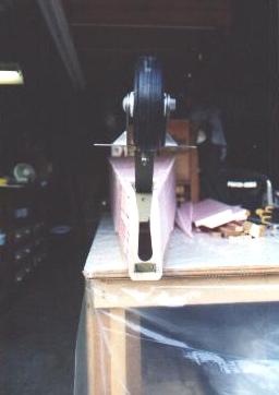
 But anyway, here is what the parts looked like, temporarily put together using whatever hardware was laying around. No, that's not an AN-grade tailwheel axle bolt, but it will be when it goes together for real.
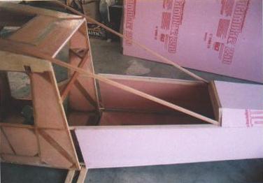
 This is what I decided to do where the rear window framing will run into the top rear deck... make a semi-bulkhead. The top piece shown here will be radiused away on its bottom edge. Clamps hold string along top longerons to help me line things up.
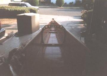
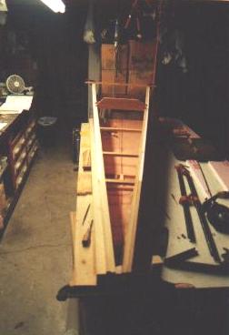 This is a view down the empennage, showing the top of my "bulkhead", as well as several temporary braces I put in between the top longerons, to straighten them while I fabricate the top deck. The sides want to twist because the top and bottom longerons aren't parallel as they run aft. A stick at the forward ends is clamped in place to hold them apart at the exact distance needed to slip into the aft end of the cabin structure. Also, I marked a centerline on the inside of the empennage floor before building up the sides... it would sure be hard to do it later, after the deck is on. The manual indicates that this line will be needed to line things up when the empennage is joined to the cabin.
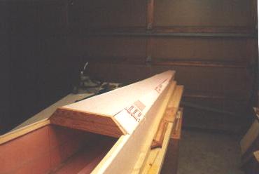 Here are the pieces of the top deck being fitted. Nothing is sanded round or smooth yet, but give it time! The empennage ends up being nice and rounded.
 This is the spring plate, which I also made of cherry wood rather than plywood... "just because". Note also the location for the access hole just forward of the spring plate. This will allow installing the hardware which holds the horiz. stab. hinges in place, as well as the tailspring bolt, and will also help when it comes time to fish the rudder cables through the sides of the tail. All the foam gets shaped and sanded; right now it's all square and full size 3/4" thickness.
 I just had to do this. Nothing is finished yet, but I had to test-fit the empennage to the cabin. Good thing, too- because I found that I need to tweak the longerons to fit the cabin. No, I didn't cut them too small; for once, I left myself enough extra wood to be able to sand down to where I need.
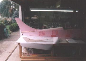 So! It begins to look like the tail of an airplane, although without the rudder it looks more like a jet. I am going to a tail design more like the L-19 than the prototype, with rounded edges. Look at an L-19 (or a Cessna 195) and you'll see what I plan to do, or take a look at my color scheme (on my home page). Anyway, the vertical stabilizer here is just taped in place for looks. It still needs a wood beam at the trailing edge.
 This is a bad shot (sun was in my face)- showing the doubler I added at the forward side of the tailplate. Just gives me more to screw the vertical stabilizer beam to. Still needs sanding to shape. I've also not yet filled and sanded the foam on the sides.
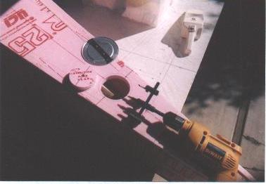 The easy way to cut inspection holes. Get a fly cutter (hole cutter); mine was about $6 at Harbor Freight, and I've used it for lots of things. Beats using my knife.
 Oh, man. Before I got the digital camera I couldn't seem to get this lighting thing right (flash didn't go off)- but this is maybe visible enough for you to see what my bulkhead looks like. I cut out some lightening holes in it. Two holes center of bottom member are where the elevator cable fairleads go. From that point aft, they diverge to hit the ends of the elevator horn. Two holes at lower corners are where the rudder cable fairleads go. There is another set of fairlead blocks back aft, just ahead of where the cables exit the tailcone. This bulkhead is where the rear window meets the tail.
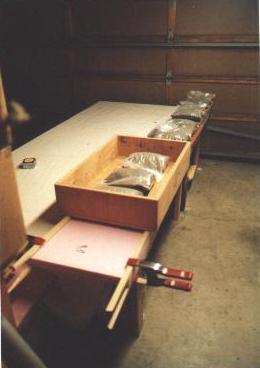
 Now this is good lighting! This is roughly what the rear window area will look like, except nothing is fitted or cut to proper length. Just gives you an idea of how much space there is behind the seat for "baggage". I have no idea what the actual capacity will be until I do CG calcs, weight and balance, but for sure it will hold a sleeping bag and light stuff (maybe 30 lbs.). Question is, will it fit Maggie (our 80 lb. pit bull), or a kid who stows away for a ride? Believe it or not, I think if I swing the seat forward or remove it, I can even unroll a sleeping bag INSIDE the airplane and camp out with my legs stuck down into the tail! It would have to be a mighty bad storm outside for me to try it, though.
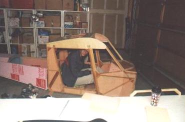 John Bouyea visited my shop (shop...ha!) and tried on the Squirrel for size. John is not as small as I am. Once again, this is before I lowered the seat to provide more headroom. I'll have to get Bou to try it again!
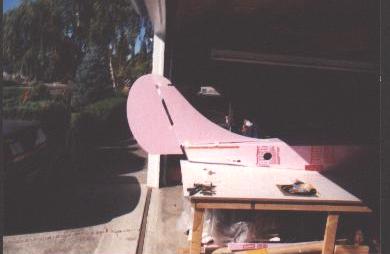 It's looking like a real tail! Here is the vertical stabilizer and rudder roughly fitted and shaped. No hinges, horns, or spars yet, but I wanted to see how it was shaping up. Again, compare this profile to an L-19, or to a Cessna 195.
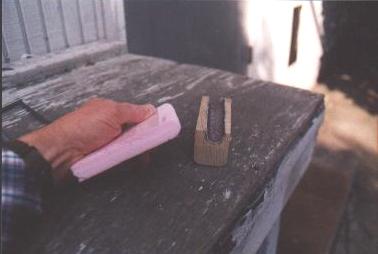 This is what I did to shape the leading edges of my tail feathers. Took a piece of coarse-grit sanding belt, cut it to fit in an airfoil- or parabola-shaped cutout in a block of wood, glued it in. It really shapes the leading edges quick and easy, leaving them ready for final sanding with medium grit.
I have to hand it to Marvin again. This has been a most enjoyable project, and far exceeds my wildest expectations for being completely satisfying and challenging. It's simple enough for a geeky nerd like me to figure out, but technical enough to be something that takes some skill to build, too. So, if you're not building yet,.........................why not?
Return to My Flying Squirrel Home Page