Restoration of Marvin's Engine
Documenting the restoration and return to running condition of the 1835cc Type I VW engine which powered Marvin's prototype Flying Squirrel.

The prototype M-19, N7238B, as it looked when loosely reassembled after arriving in Oregon in September of 2021.

This is what the plane looked like when Squirrel builder John Bouyea from Hillsboro, Oregon arrived in Norman, Indiana to rescue it from a shed
where it had been for some 18 years. The engine, which is not completely enclosed or protected, looked like what you would expect from it being in those conditions.
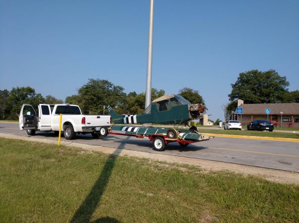
Here's what John's truck and trailer rig looked like when setting out from Indiana to come back West to Oregon with the Squirrel aboard. Wings nested
snugly under the plane, which had the engine cowling, rudder, and horizontal tail surfaces removed for the trip. Total out-and-back distance traveled, including
the run down I-5 from the Portland area to my hangar in Medford and back: about 5456 miles. Imagine making that drive at an average speed of 55 MPH and you come
up with 100 hours on the road. Whew-! Now that little drive will get your oil warmed up real good!
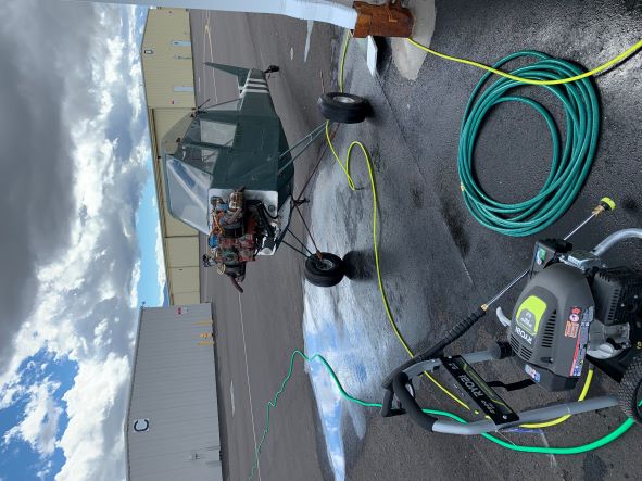
First order of business was to power wash everything that was accessible after removing the engine cowlings so that the condition of things could be evaluated.
Pretty much needless to say, there was plenty of accumulated gunk and oil on the engine and without hot water and detergent, the power washer did its best but
it was just a start. A good start though, since most of the nuts and bolts and wires could now be examined more closely.
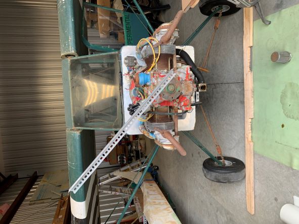
Set up in the hangar with everything dry, vacuumed out, and the wings and tail surfaces loosely reinstalled to keep everything together. A piece of perforated steel
utility angle was bolted to the prop hub to facilitate rotating the engine, which turned freely and quietly. Marvin's propeller had disappeared from the plane
sometime during the storage period in Indiana.
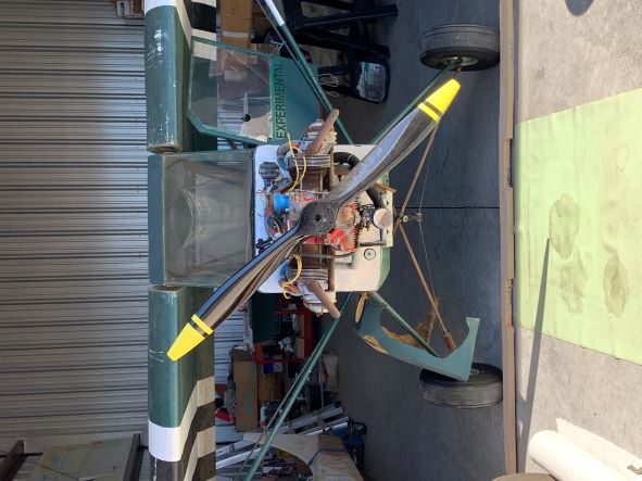
This was the way the plane and engine looked just before I began tearing into it. With the tires aired back up, it rolled much easier! I decided that the
perforated steel angle didn't do much for the looks of the plane so I pulled that off and mounted the 58x28 prop that I had Tennessee Props build for my Squirrel.
Much better, and it hand-turned the engine over just fine too. I had shipped this prop to Marvin to test-fly on the plane sometime early in 2000 and before returning
it to me he reported 3200 RPM maximum in flight and maybe 80 MPH indicated. Pretty darned good for a Flying Squirrel, and dialed back a bit to something not exceeding
3000, these planes should purr right along. Certainly comparable cruise to my Pietenpol Air Camper with Continental A75 on the nose. So now let's start the
engine teardown to see if we've got enough good engine left to make a restoration worthwhile!
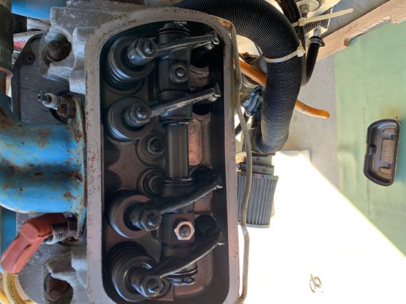 I started with the easiest stuff first... the valve covers. Here's the port side bank of rockers and I was very pleasantly surprised to find them all clean,
corrosion free, and good-looking. No obvious damage, no gunky buildup, no floppy rockers (although the valve lash on some of them was obviously more than .006").
A great start though. Valve covers, valve cover gaskets, and spring bails will get replaced in the rebuild. I thought that the chromed valve covers never did suit
the appearance or mission of the plane, plus they had a good deal of rust on them and so did the bails.
I started with the easiest stuff first... the valve covers. Here's the port side bank of rockers and I was very pleasantly surprised to find them all clean,
corrosion free, and good-looking. No obvious damage, no gunky buildup, no floppy rockers (although the valve lash on some of them was obviously more than .006").
A great start though. Valve covers, valve cover gaskets, and spring bails will get replaced in the rebuild. I thought that the chromed valve covers never did suit
the appearance or mission of the plane, plus they had a good deal of rust on them and so did the bails.
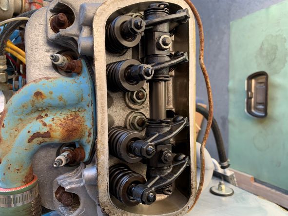
Starboard side cover came off next and that bank of rockers looked just as nice as the other side. Let's keep going!
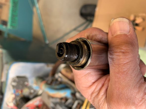 Out came the spark plugs, and although none of them had that nice dry tan appearance to them, at least they weren't showing signs of lean running and it looked like
there was a good protective oil film on things inside the cylinders. Gaps looked to be what they should have been. Spark plugs will get replaced with new ones.
Out came the spark plugs, and although none of them had that nice dry tan appearance to them, at least they weren't showing signs of lean running and it looked like
there was a good protective oil film on things inside the cylinders. Gaps looked to be what they should have been. Spark plugs will get replaced with new ones.
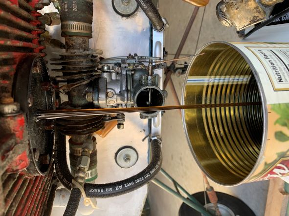 There was no sense beating around the bush... the oil had to come out to see how it looked, so I pulled off everything that needed to get out of the way of the oil dump
(details on the removed stuff to be shown later) and pulled the drain plug. Amazing! The oil looked very clean, drained smoothly from the sump, and I started getting
real encouraged about this restoration. Rather than just a post-mortem, this looked like it was clearly going to be a surgical operation that might lead to recovery!
There was no sense beating around the bush... the oil had to come out to see how it looked, so I pulled off everything that needed to get out of the way of the oil dump
(details on the removed stuff to be shown later) and pulled the drain plug. Amazing! The oil looked very clean, drained smoothly from the sump, and I started getting
real encouraged about this restoration. Rather than just a post-mortem, this looked like it was clearly going to be a surgical operation that might lead to recovery!
 The sump coverplate came off next, and as expected, it had accumulated a pretty good layer of gunk. I washed the plate in some gasoline and then strained that through
a coffee filter and allowed it to dry completely. Once dry, I spread the debris out on a piece of white paper to see what was in the gunk after the oils were taken
out of it. I was looking for anything shiny... steel, aluminum, bronze. Anything that might indicate bearing problems, cam, followers, anything. Although there were
some bright bits in there, they were all miniscule and nothing that seemed to be other than expected wear. The oil drain plug will get replaced with a new magnetic one
and the sump coverplate will get a new gasket and screen in the rebuild.
The sump coverplate came off next, and as expected, it had accumulated a pretty good layer of gunk. I washed the plate in some gasoline and then strained that through
a coffee filter and allowed it to dry completely. Once dry, I spread the debris out on a piece of white paper to see what was in the gunk after the oils were taken
out of it. I was looking for anything shiny... steel, aluminum, bronze. Anything that might indicate bearing problems, cam, followers, anything. Although there were
some bright bits in there, they were all miniscule and nothing that seemed to be other than expected wear. The oil drain plug will get replaced with a new magnetic one
and the sump coverplate will get a new gasket and screen in the rebuild.
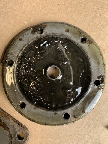
 Oil pump cover came off next and here's what the inside face of it looked like. Wear rings from the oil pump gears don't look too bad, at least they aren't so deep
that a little polishing and then honing on a whetstone won't improve the fit. If the gear faces don't ride tight against the cover, oil can squish past them from the
high pressure side to the low pressure side and effectively bypass the engine's oil galleries entirely. We'll work on this later. Coverplate will get cleaned up,
wear face polished, paint, and a new gasket in the rebuild. On the advice of my VW engine guru Bouyea, I'll also rotate the coverplate so that the gears have new metal
to run up against.
Oil pump cover came off next and here's what the inside face of it looked like. Wear rings from the oil pump gears don't look too bad, at least they aren't so deep
that a little polishing and then honing on a whetstone won't improve the fit. If the gear faces don't ride tight against the cover, oil can squish past them from the
high pressure side to the low pressure side and effectively bypass the engine's oil galleries entirely. We'll work on this later. Coverplate will get cleaned up,
wear face polished, paint, and a new gasket in the rebuild. On the advice of my VW engine guru Bouyea, I'll also rotate the coverplate so that the gears have new metal
to run up against.
...like this ;o)
...and this.
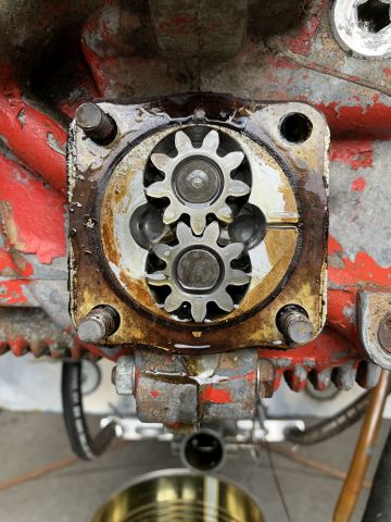
Here's the oil pump. Nothing really scary here so I assume that it can be cleaned up and continue in service. With the service that this engine will see, there isn't
really any need for a higher capacity oil pump, although they are available.
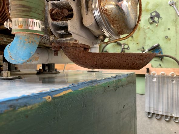
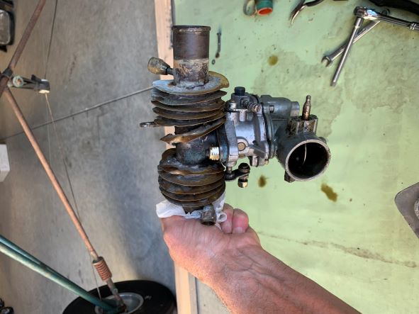 The next thing to come off was the carb with its intake manifold tee. The carb is a Zenith with ground-adjustable mixture and choke, Great Plains Aircraft model 1819
(for 1835-1915cc VW engines, according to the GPASC catalog). The parasitic creature that has wrapped itself around the intake manifold cross-tube is an intake air
preheater/oil cooler that Marvin devised and fabricated out of copper tubing with brass fins soldered onto it. As we'll see shortly, removing this parasite and cleaning up
the intake manifold was a labor-intensive operation that got pretty messy.
The next thing to come off was the carb with its intake manifold tee. The carb is a Zenith with ground-adjustable mixture and choke, Great Plains Aircraft model 1819
(for 1835-1915cc VW engines, according to the GPASC catalog). The parasitic creature that has wrapped itself around the intake manifold cross-tube is an intake air
preheater/oil cooler that Marvin devised and fabricated out of copper tubing with brass fins soldered onto it. As we'll see shortly, removing this parasite and cleaning up
the intake manifold was a labor-intensive operation that got pretty messy.
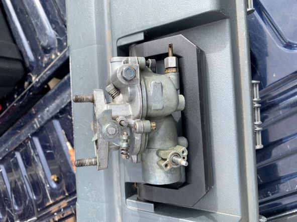 First, however, the carb came off the manifold for overhaul. It was completely disassembled, tanked in carb cleaner for degunking, mating body and bowl surfaces honed to
true them up (these carbs are notorious for leaking air around that seam since the parts are made of pot metal and rarely mate perfectly). New gaskets finished the job.
First, however, the carb came off the manifold for overhaul. It was completely disassembled, tanked in carb cleaner for degunking, mating body and bowl surfaces honed to
true them up (these carbs are notorious for leaking air around that seam since the parts are made of pot metal and rarely mate perfectly). New gaskets finished the job.
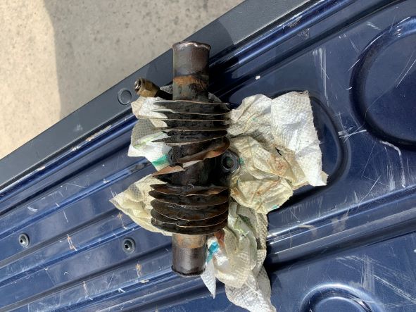 The strangled manifold got soaked in solvent and blown out, but enough oil remained in the spiral-wound tubing to make the removal work a mess of filings and oil. I saw no
purpose in keeping the thing as it was, especially since Marvin reported that it seemed to make no difference in either controlling carb ice or significantly cooling the oil.
The strangled manifold got soaked in solvent and blown out, but enough oil remained in the spiral-wound tubing to make the removal work a mess of filings and oil. I saw no
purpose in keeping the thing as it was, especially since Marvin reported that it seemed to make no difference in either controlling carb ice or significantly cooling the oil.
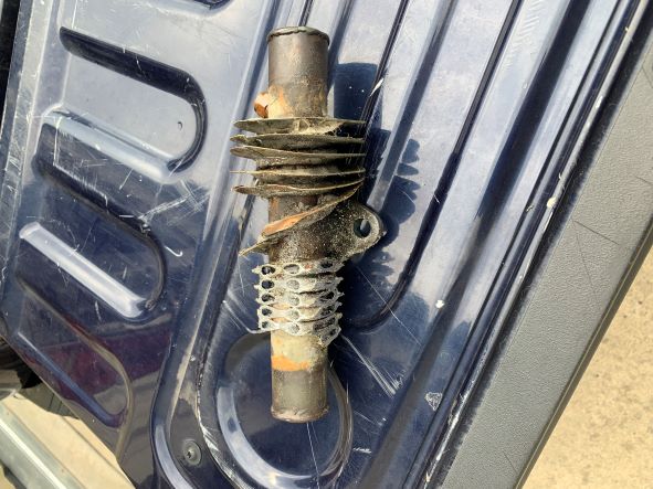 Here's the removal surgery beginning. The first pass was through the bandsaw, to quickly remove mass and fins to make it easier to handle. Once the honeycombed passages were open,
the oily mess began. I'll skip that part, and the part with the abrasive cutoff wheel, and the parts with coarse files and the coarse-grit disc sander and everything else that I
had to throw at it to get back down to bare parent metal.
Here's the removal surgery beginning. The first pass was through the bandsaw, to quickly remove mass and fins to make it easier to handle. Once the honeycombed passages were open,
the oily mess began. I'll skip that part, and the part with the abrasive cutoff wheel, and the parts with coarse files and the coarse-grit disc sander and everything else that I
had to throw at it to get back down to bare parent metal.
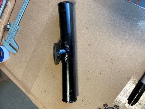 Final result after a little polishing, degreasing, and some paint. Ready to reinstall.
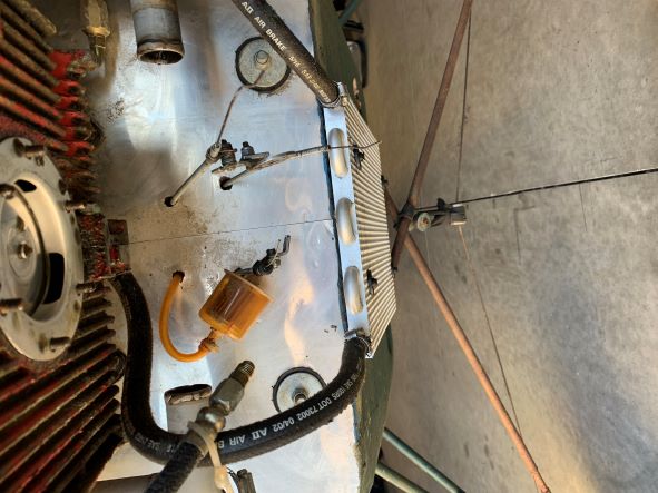 A lot to see here, but this is how things looked under the engine once the engine control cables, oil hoses, and fuel line were disconnected and the carb and intake manifold tee
were removed. Marvin ended up adding this flat finned-tube oil cooler on the bottom of the airplane and said it worked well enough. Oddly enough, he had it positioned with the
fins opposing the flow of oncoming air rather than encouraging air to flow between the fins and over the tubes. Hot oil from the pump comes into the cooler through
the hose on the left and returns to the engine's oil galleries through the hose on the right. The hoses he used are some heck-for-stout hydraulic fluid hoses that are heavy and
all but impossible to cut through. All of that was removed and not reused in the restoration since I converted the oil cooling to a top-mount pancake style, as we'll see presently.
The thin aluminum oil screen up in the engine sump gets pulled and replaced. Also improved in the restoration were the openings through the firewall for the Bowden cables, lines,
and wires... each of which received stainless 2-piece shields to tidy up the installation. The old fuel filter and hardened/yellowed fuel tubing were discarded and a different
fuel setup used in the restoration.
A lot to see here, but this is how things looked under the engine once the engine control cables, oil hoses, and fuel line were disconnected and the carb and intake manifold tee
were removed. Marvin ended up adding this flat finned-tube oil cooler on the bottom of the airplane and said it worked well enough. Oddly enough, he had it positioned with the
fins opposing the flow of oncoming air rather than encouraging air to flow between the fins and over the tubes. Hot oil from the pump comes into the cooler through
the hose on the left and returns to the engine's oil galleries through the hose on the right. The hoses he used are some heck-for-stout hydraulic fluid hoses that are heavy and
all but impossible to cut through. All of that was removed and not reused in the restoration since I converted the oil cooling to a top-mount pancake style, as we'll see presently.
The thin aluminum oil screen up in the engine sump gets pulled and replaced. Also improved in the restoration were the openings through the firewall for the Bowden cables, lines,
and wires... each of which received stainless 2-piece shields to tidy up the installation. The old fuel filter and hardened/yellowed fuel tubing were discarded and a different
fuel setup used in the restoration.
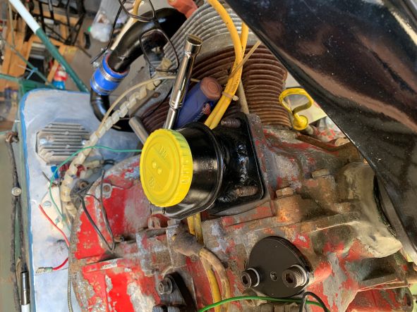
 Up on top, I removed enough of the previous oil system apparatus to allow me to test-fit a pancake-style oil cooler where it should go. It fit fine, so that's the direction I'll
take the oil system. This is the arrangement that I plan to use on my own 1835 with pressure cowl and baffling, but that's a story for another day. Here you see that the oil filler/
crankcase breather/oil mist separator has been removed and the old breather hose (oil-browned plastic tubing up against the firewall) is ready to yank out. The ignition coil
has also been demounted so as to swing it out of the way. It tested 'good', is still serviceable, and will be cleaned and reused.
Up on top, I removed enough of the previous oil system apparatus to allow me to test-fit a pancake-style oil cooler where it should go. It fit fine, so that's the direction I'll
take the oil system. This is the arrangement that I plan to use on my own 1835 with pressure cowl and baffling, but that's a story for another day. Here you see that the oil filler/
crankcase breather/oil mist separator has been removed and the old breather hose (oil-browned plastic tubing up against the firewall) is ready to yank out. The ignition coil
has also been demounted so as to swing it out of the way. It tested 'good', is still serviceable, and will be cleaned and reused.
 The mounting pad for the oil cooler has been cleaned and prepped for the new cooler. I sure wish I had started out determined to strip the engine of its accessories, swing it off
the airframe on my engine hoist, strip and clean the cases, and repaint them. That does not look good, it doesn't make me happy to see it left this way, but it was never in my plan
to go that far with the restoration and the deteriorated paint job doesn't affect the engine operation.
The mounting pad for the oil cooler has been cleaned and prepped for the new cooler. I sure wish I had started out determined to strip the engine of its accessories, swing it off
the airframe on my engine hoist, strip and clean the cases, and repaint them. That does not look good, it doesn't make me happy to see it left this way, but it was never in my plan
to go that far with the restoration and the deteriorated paint job doesn't affect the engine operation.
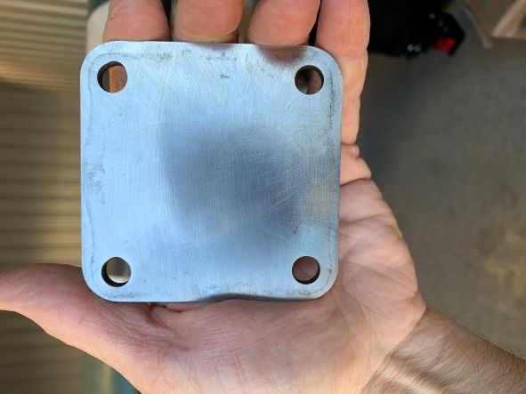
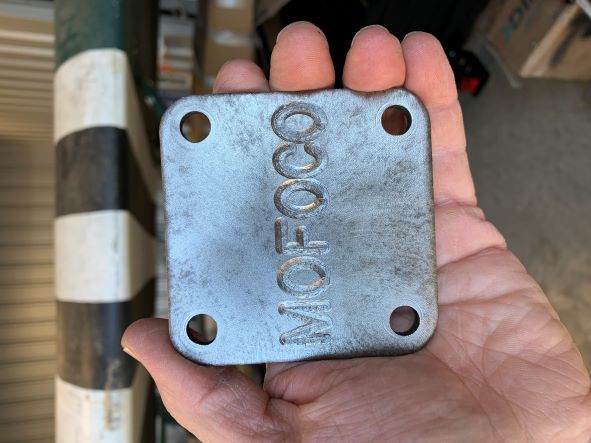
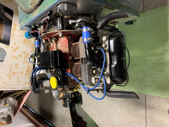
 Cleaned up and painted dipstick and oil filler/breather/separator in their places. Fuel pump blank-off plate to the left of it has been cleaned, painted, and reinstalled with a new gasket. In the background,
the stripped, cleaned, painted, and re-fitted port side intake manifold is visible with its new flexible joiner. Electrical wiring is still untouched at this point, so don't look
at it ;o) Oops... now that's all you see, right? ;o)
Cleaned up and painted dipstick and oil filler/breather/separator in their places. Fuel pump blank-off plate to the left of it has been cleaned, painted, and reinstalled with a new gasket. In the background,
the stripped, cleaned, painted, and re-fitted port side intake manifold is visible with its new flexible joiner. Electrical wiring is still untouched at this point, so don't look
at it ;o) Oops... now that's all you see, right? ;o)
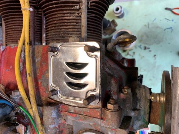 Here's the oil mist separator that fits in under the filler/breather. Once again listening to my VW guru Bouyea, I positioned the separator as recommended such that oil naturally runs
down the inverted louvers and back into the crankcase, and the rotating crankshaft and moving parts inside the case tend to fling oil droplets away from the louvered openings, not
into them. Some VW assembly manuals have the separator positioned exactly opposite this, against all logic.
Here's the oil mist separator that fits in under the filler/breather. Once again listening to my VW guru Bouyea, I positioned the separator as recommended such that oil naturally runs
down the inverted louvers and back into the crankcase, and the rotating crankshaft and moving parts inside the case tend to fling oil droplets away from the louvered openings, not
into them. Some VW assembly manuals have the separator positioned exactly opposite this, against all logic.
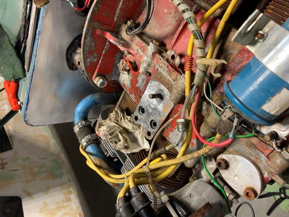
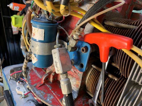 Here's what the original oil setup looked like on top of the engine. Oil drawn from the sump was pumped up through the oil relief valve to the blue adapter fitting and out through the small
aluminum block to the remote oil cooler under the plane. The oil temperature probe is stuck into the same block, opposite the hose leaving to the oil cooler, to sense the oil temperature.
The cooled oil then returns back through a hose into the other port in the blue fitting and down to the drilled oil galleries to cool and lubricate all the bearings and lifters, and then
returns down into the sump. The small diameter Nylaflow tube on the right in the picture comes out of the block through a 1/8" NPT tapping and goes to the mechanical oil pressure gauge
on the instrument panel. Visible at the top rear on the firewall are a ballast resistor (white object; determined not to be necessary with the Bosch Blue ignition coil on this engine and
discarded in the rebuild) and the dynamo voltage regulator (the cast, finned object). More on those later, when we get to ignition. Man is that flaking red paint ugly!
Here's what the original oil setup looked like on top of the engine. Oil drawn from the sump was pumped up through the oil relief valve to the blue adapter fitting and out through the small
aluminum block to the remote oil cooler under the plane. The oil temperature probe is stuck into the same block, opposite the hose leaving to the oil cooler, to sense the oil temperature.
The cooled oil then returns back through a hose into the other port in the blue fitting and down to the drilled oil galleries to cool and lubricate all the bearings and lifters, and then
returns down into the sump. The small diameter Nylaflow tube on the right in the picture comes out of the block through a 1/8" NPT tapping and goes to the mechanical oil pressure gauge
on the instrument panel. Visible at the top rear on the firewall are a ballast resistor (white object; determined not to be necessary with the Bosch Blue ignition coil on this engine and
discarded in the rebuild) and the dynamo voltage regulator (the cast, finned object). More on those later, when we get to ignition. Man is that flaking red paint ugly!
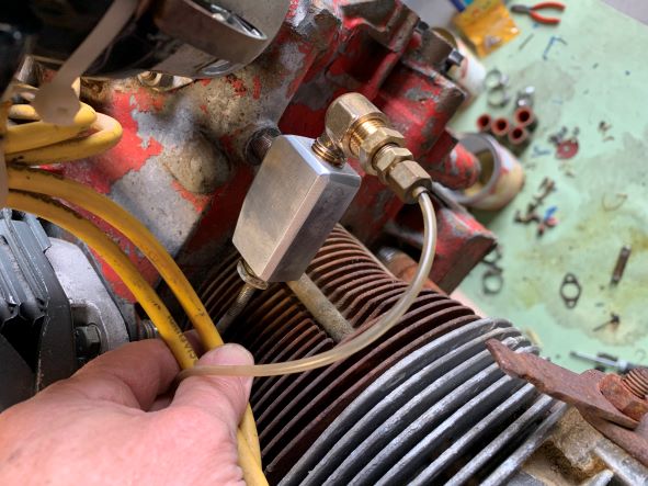 The new oil setup for the restoration has the small aluminum block relocated to the oil pressure takeoff tapping on the engine case and is reconfigured to have the oil temperature off the aft
end of the block and the oil pressure taken off the front of it.
The new oil setup for the restoration has the small aluminum block relocated to the oil pressure takeoff tapping on the engine case and is reconfigured to have the oil temperature off the aft
end of the block and the oil pressure taken off the front of it.
Please note: THIS IS NOT CONSIDERED TO BE AN AIRWORTHY ARRANGEMENT.
The relatively small 1/8"NPT tapping and nipple are not beefy enough to support this much cantilevered mass on a vibrating engine that is also subject to positive and negative G forces
sufficiently large to fatigue or fracture the small nipple. If such a thing were to occur, high-pressure oil would be pumped and sprayed out of the engine into the engine compartment and
all over everything in there. No bueno.
Because this restoration is on a non-airworthy airplane and is intended for static ground runs of the engine only, these components have been reused in a configuration
that would not otherwise be acceptable or good practice.
 Here's what the very short exhaust stacks looked like when the plane came out of storage. We will not be replacing these under this restoration, but we will be taking care of them just a bit.
Note the as-yet unfinished intake manifold and rusty chromed valve cover and its bail. At least there's no flaking, peeling red paint in this picture ;o)
Here's what the very short exhaust stacks looked like when the plane came out of storage. We will not be replacing these under this restoration, but we will be taking care of them just a bit.
Note the as-yet unfinished intake manifold and rusty chromed valve cover and its bail. At least there's no flaking, peeling red paint in this picture ;o)
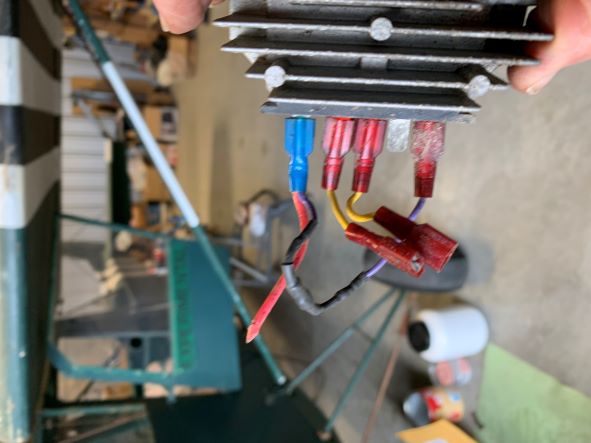 Output regulator for the Jo** De*** (can't mention any names) dynamo. Because a dynamo has fixed permanent magnets, it does not require any external power to provide excitation and when it turns,
it produces alternating current but in an unregulated condition. The faster it turns, the more power it can produce- but besides rectifying the AC to DC, the regulator keeps the voltage constant
and prevents overcharging of the battery, which stores energy to power the ignition and accessories. Judicious selection of the pulley that drives the dynamo off the back end of the engine
will at least hold its maximum speed (and output) to the amount of power that is anticipated to be needed, and Marvin selected a pulley from a washing machine (or laundry dryer; not certain which)
for this duty. In this application, with no electrical instruments, radios, lights, or anything other than ignition, the setup on this plane has excess capacity so the regulator is
always dumping excess to ground. All wiring will be reworked and the dynamo/regulator retained.
Output regulator for the Jo** De*** (can't mention any names) dynamo. Because a dynamo has fixed permanent magnets, it does not require any external power to provide excitation and when it turns,
it produces alternating current but in an unregulated condition. The faster it turns, the more power it can produce- but besides rectifying the AC to DC, the regulator keeps the voltage constant
and prevents overcharging of the battery, which stores energy to power the ignition and accessories. Judicious selection of the pulley that drives the dynamo off the back end of the engine
will at least hold its maximum speed (and output) to the amount of power that is anticipated to be needed, and Marvin selected a pulley from a washing machine (or laundry dryer; not certain which)
for this duty. In this application, with no electrical instruments, radios, lights, or anything other than ignition, the setup on this plane has excess capacity so the regulator is
always dumping excess to ground. All wiring will be reworked and the dynamo/regulator retained.
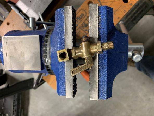 Fuel shutoff valve. This mounts to the starboard side of the instrument panel in Marvin's plane. I completely dismantled, cleaned, and reassembled the valve for reinstallation.
Curiously, the lever handle has no stops, so visual verification of fully open or closed positioning is needed or it could stay just a hair open or closed.
Fuel shutoff valve. This mounts to the starboard side of the instrument panel in Marvin's plane. I completely dismantled, cleaned, and reassembled the valve for reinstallation.
Curiously, the lever handle has no stops, so visual verification of fully open or closed positioning is needed or it could stay just a hair open or closed.
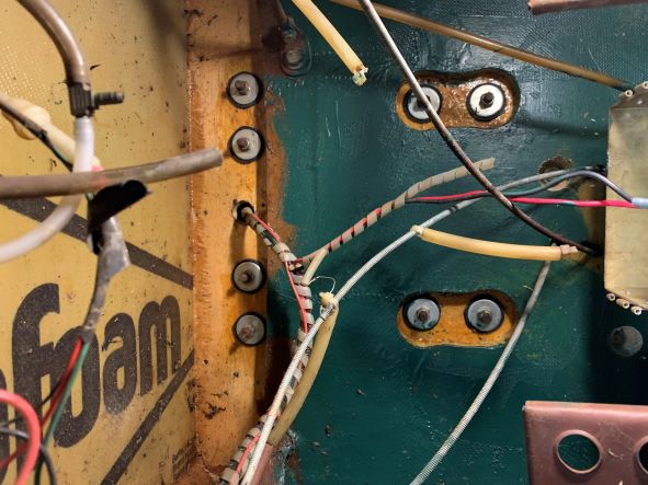 Now let's see... how do I get out of this maze? Where am I? Well, this is a view looking straight at the aft face of the firewall, inside the cabin, under the instrument panel.
Two horizontally-arranged sets of bolts with large washers at the top are the upper engine mounts and the two vertically-arranged sets are the lower engine mounts. Below them is the lower half
of the battery box with the red + and black - battery wires, along with a bunch of other stuff. Port side rudder pedal on the left, with the holes in it. We're going to sort out this
mess. Marvin used surgical tubing here and there as "bungees" to hold things out of the way of other things, but we're going to eliminate all that spaghetti eventually so hang tight.
Now let's see... how do I get out of this maze? Where am I? Well, this is a view looking straight at the aft face of the firewall, inside the cabin, under the instrument panel.
Two horizontally-arranged sets of bolts with large washers at the top are the upper engine mounts and the two vertically-arranged sets are the lower engine mounts. Below them is the lower half
of the battery box with the red + and black - battery wires, along with a bunch of other stuff. Port side rudder pedal on the left, with the holes in it. We're going to sort out this
mess. Marvin used surgical tubing here and there as "bungees" to hold things out of the way of other things, but we're going to eliminate all that spaghetti eventually so hang tight.
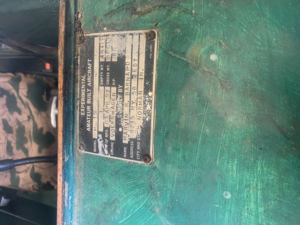 I happened to notice that Marvin's airplane's certification date was April 3, 1997. In a moment of sentimentality about that, I took some in-progress status photos of the engine restoration
and sent them to the Barnard family on April 3, 2022... the 25th "birthday" of N7238B. Here are those photos, but we're not done with the work yet!
I happened to notice that Marvin's airplane's certification date was April 3, 1997. In a moment of sentimentality about that, I took some in-progress status photos of the engine restoration
and sent them to the Barnard family on April 3, 2022... the 25th "birthday" of N7238B. Here are those photos, but we're not done with the work yet!
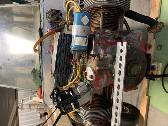
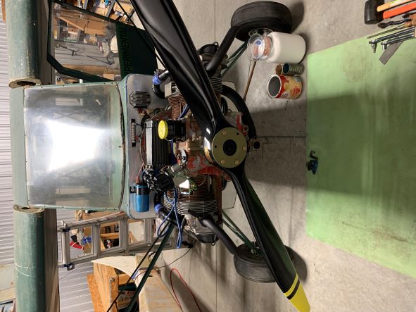 Yes, I know that not all the prop bolts are installed. The ignition coil has been relocated to its new place on the firewall. Where the ballast resistor used to be on the firewall, and since
there were already holes there, I installed a barrier strip on which to land all ground leads and shield drains. It's a good idea to establish a common reference ground point to reduce the possibility
of circulating currents due to differences in potential between grounds that are separated. It should also help to reduce radio interference and static. The cleaned and painted oil cooler is mounted
on top; new spark plug wires are run but not yet dressed. Exhaust stacks are wearing rattle-can black BBQ grill paint.
Yes, I know that not all the prop bolts are installed. The ignition coil has been relocated to its new place on the firewall. Where the ballast resistor used to be on the firewall, and since
there were already holes there, I installed a barrier strip on which to land all ground leads and shield drains. It's a good idea to establish a common reference ground point to reduce the possibility
of circulating currents due to differences in potential between grounds that are separated. It should also help to reduce radio interference and static. The cleaned and painted oil cooler is mounted
on top; new spark plug wires are run but not yet dressed. Exhaust stacks are wearing rattle-can black BBQ grill paint.
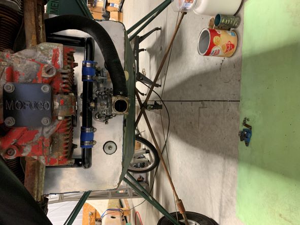 Underneath, we see the carb mounted to its newly-refinished and re-fitted intake manifold, the carb and carb heat box, and the refinished and rotated oil pump cover plate. (That little touch is for you, Bou ;o)
Faintly visible behind the black flex tubing that carries heated air to the carb heat box is the lawn tractor combination fuel shutoff, fuel filter, and water separator "gascolator".
Underneath, we see the carb mounted to its newly-refinished and re-fitted intake manifold, the carb and carb heat box, and the refinished and rotated oil pump cover plate. (That little touch is for you, Bou ;o)
Faintly visible behind the black flex tubing that carries heated air to the carb heat box is the lawn tractor combination fuel shutoff, fuel filter, and water separator "gascolator".
 Starboard side. Later on we'll take a closer look at the electrical wiring and the spaghetti that connects the engine to the instruments but right now we're just looking at the big picture.
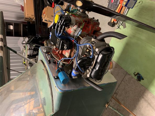
 Port side of the engine, which I think may be its best side ;o) Visible in this shot is the main ground wire from the engine case to the ground reference barrier strip as well as the dynamo, which is
sandwiched down in there between the back of the engine and the firewall. It's VERY tight in there due to the short engine mount standoffs. Still missing in this picture is the oil mist separator
tube which will run aft from the separator and turn down along the firewall to spit downwards. It sure will be nice to hear some crackling from those short little exhausts! In the next and final
phases of this rebuild, I'll be tying up loose ends such as final torqueing the prop bolts, filling the crankcase with oil, gapping and installing the new spark plugs, setting the valve lash, checking
the static timing of the ignition, completing the electrical wiring, connecting the fuel supply from one of the wing tanks down to the carb through the new gascolator and overhauled fuel shutoff valve,
moaning some more about the ugly chipping and flaking red paint, and hopefully doing a barefoot Cherokee dance to encourage De-Wa's freshened-up engine to come to life! Marvin was always more
comfortable when he was barefoot, being a country boy and all. Clever country boy though!
Port side of the engine, which I think may be its best side ;o) Visible in this shot is the main ground wire from the engine case to the ground reference barrier strip as well as the dynamo, which is
sandwiched down in there between the back of the engine and the firewall. It's VERY tight in there due to the short engine mount standoffs. Still missing in this picture is the oil mist separator
tube which will run aft from the separator and turn down along the firewall to spit downwards. It sure will be nice to hear some crackling from those short little exhausts! In the next and final
phases of this rebuild, I'll be tying up loose ends such as final torqueing the prop bolts, filling the crankcase with oil, gapping and installing the new spark plugs, setting the valve lash, checking
the static timing of the ignition, completing the electrical wiring, connecting the fuel supply from one of the wing tanks down to the carb through the new gascolator and overhauled fuel shutoff valve,
moaning some more about the ugly chipping and flaking red paint, and hopefully doing a barefoot Cherokee dance to encourage De-Wa's freshened-up engine to come to life! Marvin was always more
comfortable when he was barefoot, being a country boy and all. Clever country boy though!
In loving memory of Marvin R. Barnard...
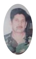
December 3, 1958 ~ February 14, 2004
...in memory of whom I should probably be BAREFOOT when we make the first engine startup after restoration!
(This page was created December 13, 2022)(First phase completed December 22, 2022)
"I wisdom dwell with prudence, and find out knowledge of witty inventions." -Proverbs 8:12
©2023 taildrags@hotmail.com