M-19 Engine
VW Engine and Installation
revised November 5, 2001
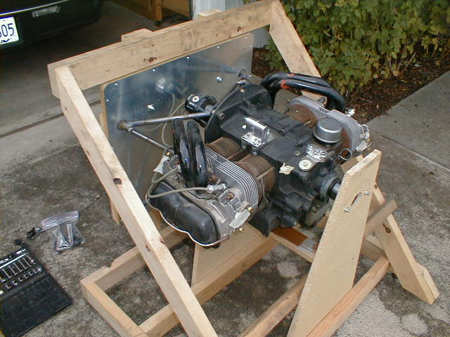
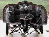
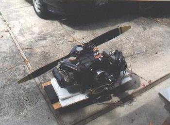
Here's the engine in a fixture/jig that I built so Jeff Sterling could weld up my engine mount. It will also serve as a stand that I can use to fabricate the engine cowling and manifolds without having the engine mounted on the airplane (my garage is too small!) In this photo, I've just gotten the mount back from Jeff so it's not yet sandblasted or primed, and temporary steel spacers are installed where rubber isolators go at the engine mount points. All hardware is "hardware store"; permanent hardware will be standard AN. Orange goop on the intake manifolds is the sealant that the previous owner used around the baffles. The installation in the M-19 uses no baffles.
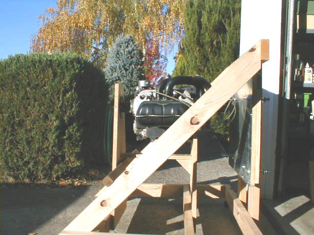
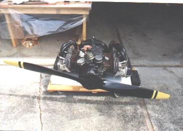
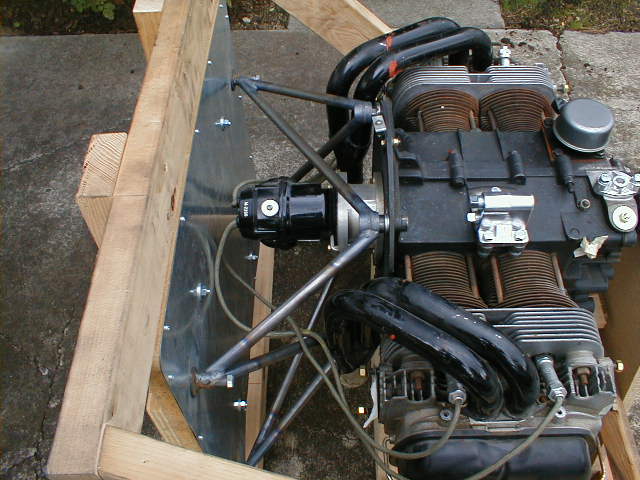 Side view of the engine, stand, and jig. Everything fits nicely!
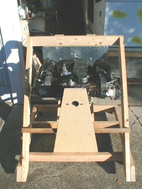
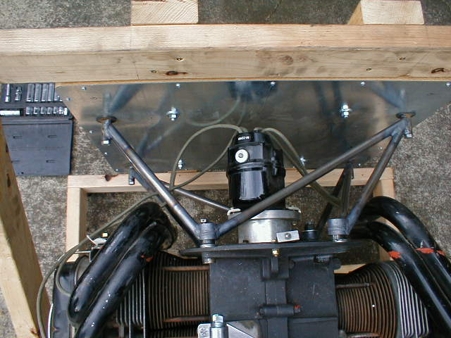 Top/front shot of the engine, stand, and jig. The space between the engine and firewall is a bit more than on Marvin's prototype due to my engine having a rear-mount magneto. Space is about 3" more than stock.
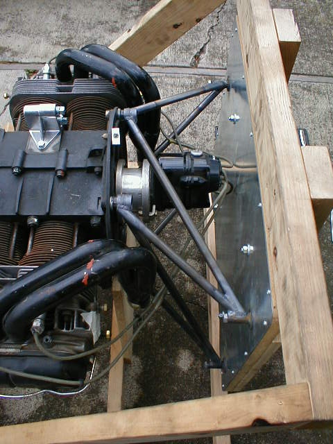
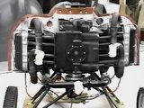
 Another angle of the engine and mount. Visible is the "tower" where the oil cooler goes on the stock engine. This tower diverts the oil to the remote mount oil filter and oil cooler, both of which will be mounted on the firewall. Masking tape covers the oil pressure tapping just below where the distributor goes in the stock VW. I've installed a plug in the hole, since I'm using a magneto. Distributor drive gear, shims, and mechanical fuel pump were also removed.
November 5, 2001 Update
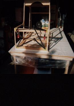
This is the engine stand that I made so I could get my engine mount welded up. It's just cheap 2x4 stud framing on some little casters so I can roll it around. I made a fake firewall, faced it with galvanized sheet metal from the duct fabrication shop, mounted it to some 3/4" particle board, and laid out all the mounting points. I then rigged up the stand framing to hold my engine as tight as I could get it to the firewall while still leaving clearance between the magneto wires and the firewall. This puts the engine several inches further from the firewall than Marvin's stock setup, so I need to look at weight and balance. However, I don't have a battery, dynamo, or electrical system... plus, I have a heavier tailwheel setup than stock, plus I've added a bit of extra framing in my aft cabin for float mounts, so hopefully I won't have too much trouble getting the CG situation back to where it needs to be. When the mount is built, I'll remove the stuff that's holding the engine up right now, and use this same stand/jig for building my cowling. Since the "fake" firewall on the stand is exactly the same as the one on the airplane, that should be a snap.
 Here's another shot of the stand/jig. I can't wait to hear that engine run!
October, 2000
Bottom view
Side view
Top view
This is the 1835cc Volkswagen engine which I bought from Tom Andersen in Florida. It is normally aspirated, carbureted (Zenith), has a single Slick magneto for ignition, no starter or alternator (no accessory case), and was built up from a Great Plains Aircraft Supply kit. It is nominally rated at 65 HP (limited to 5 minutes at 3600 RPM for takeoff power), cruise output is about 60 HP at 3400 RPM. Tom says that the engine ticks over nicely at low idle, starts with an easy flip of the prop since it has an impulse-coupled magneto, and only has 5.5 hrs. on it since being built and subsequently removed from a KR which had the roof of its hangar collapse on it.
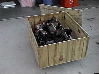
Here is the engine crated up and ready to UPS from Florida. Tom had promised me he would paint large red "up" arrows and lettering on it. (But can UPS handlers read?) ;o) The plywood from the crate has served many purposes, including making my seat and rudder pedal mockups. The carrying handles were installed on a Corvair crankshaft shipping crate (the Corvair is a whole 'nother story; it's for the KR). Nothing is wasted!
The engine was set up for use in a KR with pressure cowl. It had full baffling for use inside a full cowling as used on the KR, and had a standard KR type engine mount.
The mounting points appeared to correspond quite well with the standard firewall cross-supports on the M-19 cabin, but it turned out to place the engine a couple of inches too high to properly locate the thrust line for the M-19. Too bad, because the mounting pads landed in the perfect locations! Another consideration in using this type of mount (as opposed to the direct mount to the firewall as detailed in the construction manual) is that this mount will place the engine at least 5" forward of the design/prototype. This will affect C.G., but it is unclear at this point exactly how much this will be on my airplane since I'm using a larger tailwheel and a few other things aft of CG. We shall see!
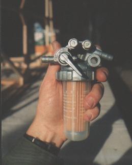
This is the fuel gascolator I'll be using. It's from my local Kub*ta lawn tractor dealer, and as you can see, it includes a shutoff valve for servicing the disposable element. The one thing it doesn't have is a quick-drain, so I'll still need a drain at the low point of my fuel system. I'll also be safety-wiring the big spin-off top of the filter bowl so it doesn't loosen itself while operating my "lawn tractor" ;o). The gascolator mounts with one bolt through the firewall, plus a 'pip' which will mate with a small hole or indentation, to keep the assembly from turning. This unit costs way less than the aviation gascolators, and is readily available.

Here's my daughter Bethany with my Tennessee Props "De-Wa Deluxe" propeller. It weighs somewhere between 4 and 5 lbs. and cost less than $250 including shipping. So far, Tennessee Props is the "unofficial propeller" for the M-19 Flying Squirrel. Contact Larry Breece at tpi@tn-props.com
Here is a shot of my engine, with prop temporarily hung in place. The neighbors really sat up when I was out messing with this ;o) Normally, I keep the engine on the mechanic's creeper, tucked under my building table where it will stay clean. I'm working on having Jeff Sterling build up my engine mount right now, planning on hanging the engine in a few months when I get the fuselage on its gear.
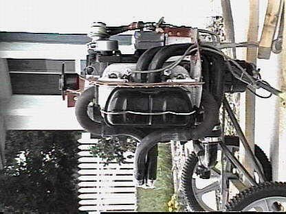
 Another shot of the engine. Orange goop is where the baffling was at one time (when the engine was in the KR it came out of). Cylinder barrels are a bit rusty from the Florida climate where it used to be, but I'll clean it up later and get it looking nice.
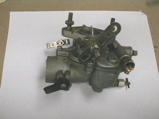
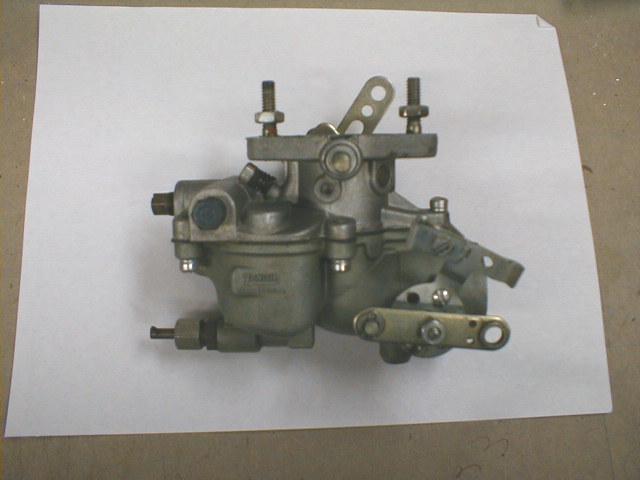 Side view of the Zenith carb I'm using. Quite a clean and simple updraft design, and it's reconfigurable to have any of the functions or connections on either side. That is, the throttle, choke, and fuel inlet can be on either side since the shafts and ports are duplicated on both sides.
 Bottom of the Zenith carb, showing the mixture adjustment screw. It's the main jet adjustment needle.
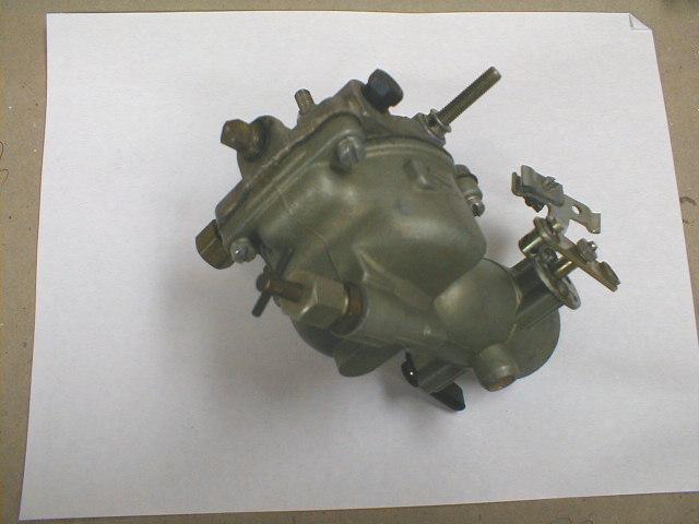
 The other side of the carb.
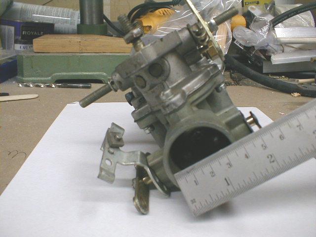 Front, or throat view of the carb. This is the inlet side, where filtered air comes in from the carb heat box.
So, if you're not building yet.......why not??
Return to My M-19 Project