M-19 Landing Gear
M-19 LANDING GEAR
Updated October 30, 2000
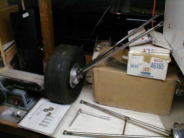 Here is one of the main landing gear legs for my M-19, loosely fitted together with an uninflated tire, just to see how it shapes up. I'm surprised at the size of the tires; they are "mini-tundra tires". Sidewall markings show them to be turf tires, probably for lawn tractor or golf cart use (from Wicks Aircraft Supply).
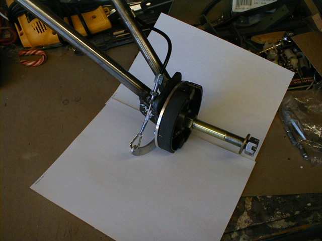
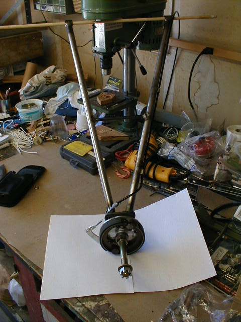 Here's a view of one of the gear legs including temporary brake actuating cable setup. Two small ring guides were brazed onto the leading edge of the gear leg to guide the cable down, then the cable adjuster and actuating arm are mounted on the trailing side of the gear to prevent damage during off-airport landings.
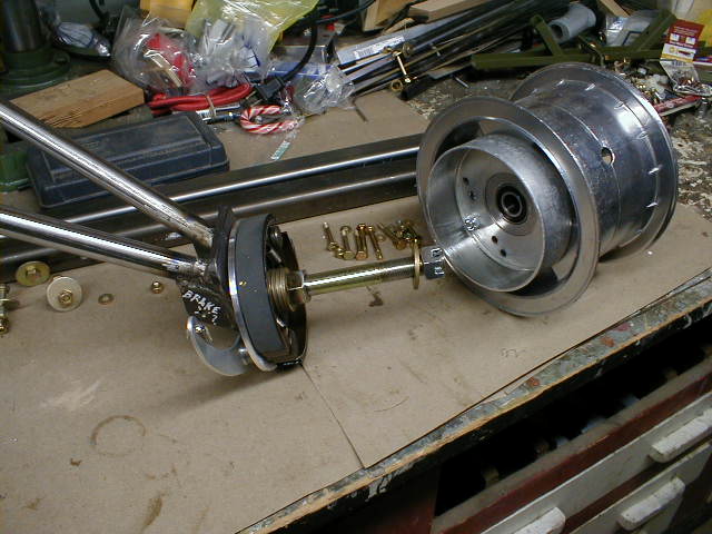 Here is an "exploded" view of one of the gear. I used 7" long Grade 8 bolts due to the addition of brakes. The washers seen between two nuts have been replaced with a spacer instead (see next photos). Brakes are 4-1/2" Azusa, somewhat of a rough fit and finish. Again, from Wicks Aircraft. And pay no attention to the half-eaten candy cane on the table there; I keep stuff like that around from Christmas then forget to finish eating it ;o)
 So here's another view of the "exploded" brake assembly, showing how I modified the stock setup to accommodate the brakes. The spacer and double-nut place the brake backing plate/brake shoe assembly at the proper depth into the drum, which is bolted to the wheel. Then a washer and castellated nut hold the wheel assembly to the axle. As mentioned, I had to lengthen my axles a bit over stock.
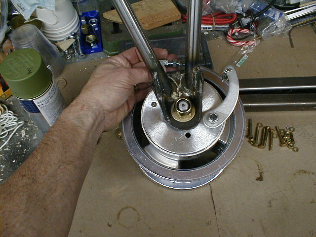 This gives you an idea of the brake cable geometry I'm trying to achieve. A nut has been welded in place to hold the cable tensioner more or less where I'm holding it in this picture (see next photo). A small tab has also been welded on, with a short pin which will index the hole you see in the brake backing plate and keep it from turning.
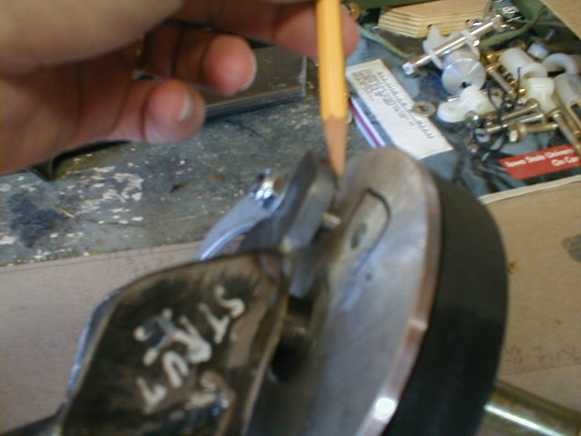 Here's the index pin which holds the backing plate from turning.
 Here's the brake setup, showing how the cable and tensioner will fit (a piece of twine has been temporarily run where the brake cable will be).
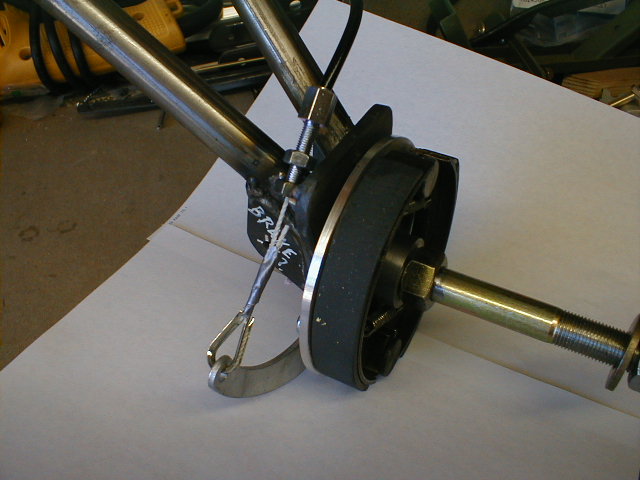 Here's the setup, showing how the cable will run.
 Here's a view of the main landing gear spring strut with spring. This is the spring called for in the materials list, from McMaster-Carr. I think it is rated about 460 lbs. at full deflection.
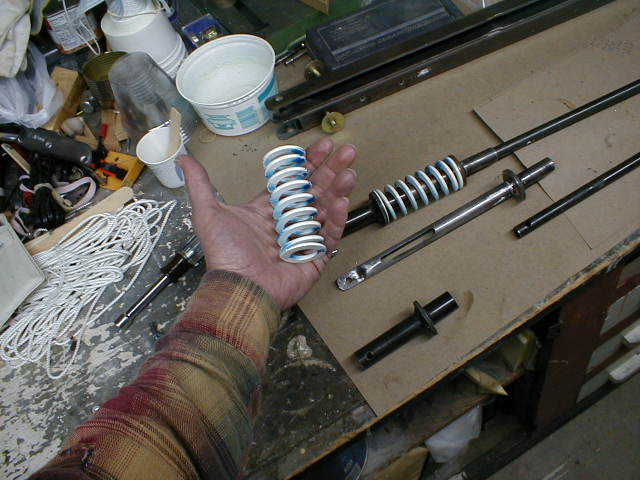
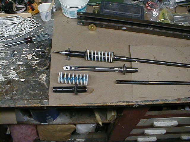 Here's a view of the parts and pieces of the sliding tubes and spring which make up the spring struts.
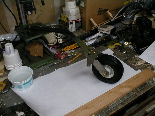 My tailwheel assembly. Spring is the one called for in the manual, notched at the aft end to receive the pivot (which I fitted with a grease Zerk). Tailwheel bracket is fabricated of stainless, "just because". My tailwheel is a bit larger than stock, 6" rather than 4", semi-pneumatic.
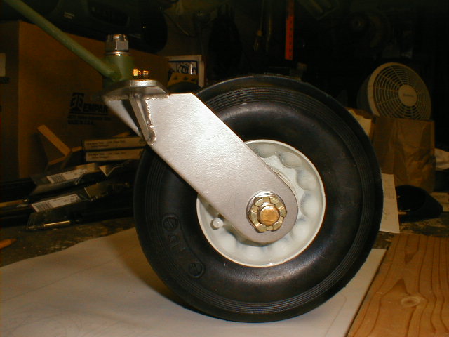 Close-up of the tailwheel bracket, showing Zerks on the pivot and on the axle bearings.
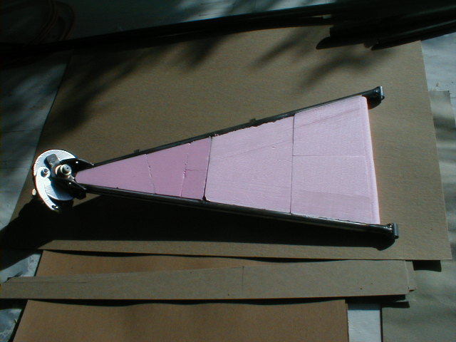 This is what I'm doing with my gear legs. The prototype has "open" legs, but I'm infilling mine with foam and will glass over them (I don't want to get into fabric covering them, though it would be lighter). I found that the foam infill has to be made up of pieces to get it into those angled spots. I sanded concave hollows into the sides of the foam pieces to nestle around the gear leg tubes. This is where my foam scrap bin comes in handy ;o)
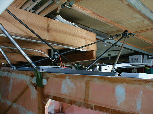 And here's how the landing gear legs and spring struts all come together on their mounting brackets.
So... if you're not building yet, why not??
Return to Main Flying Squirrel Page