INSTRUMENTS/INTERIOR
N2069Z'S INSTRUMENT PANEL AND INTERIOR
Updated October 20, 2000
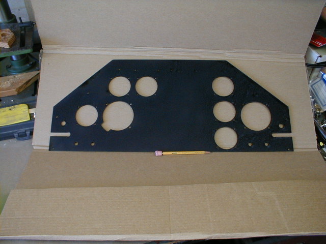
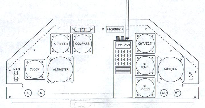 This is the proposed layout (revision no. 2,348 or so!) of my instrument panel. The bottom piece, below the heavy line, was actually going to be folded back to form a stiffener/hem but due to the inherent stiffness of the metal that the panel is made out of the flange wasn't done. The dashed line along the upper edges represents the line of the foam top deck behind the panel. Instruments are all standard stuff; the airspeed is a small (i.e. cheap) unit reading up to 120 MPH. I have a single Westach CHT/EGT and a Westach tach/hour meter which runs off the magneto (I have no electrical system). I wanted an hour meter, but all the Hobbs types I looked at need electricity. I had Westach add range markings on the tach for my 1835 VW. The fuse just to the right of the tach is for the tach itself (Westach recommends a fuse). Westach recommends keeping this tach away from the mag compass, which is why I tried to keep them as far apart as possible.
Oil pressure and temp. are mechanical units. Along the bottom are choke, mixture, cabin air and cabin heat. My mag switch is at far left. I have a small slide-open window within the port side forward window, allowing me to reach in and operate the choke, mixture, mag, and throttle through the window while prop-starting the engine. Remember, the VW rotates CCW as you look forward, so standing at the port side of the airplane behind the prop, I pull the prop through with my left hand and operate the controls with my right, through the window.
I've left space in the center of the panel for mounting a handheld COM (an Icom IC-A4 Sport, which actually doesn't look like the image), and maybe my handheld GPS (Magellan GPS 2000)just to the left of it, if it'll work there.
The panel is made of .062" 6061-T6 aluminum, cut using waterjets (see website at www.waterjet.net , Carmin Industries. It came out terrific!
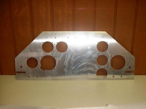 Here's how the panel looked when I got it from CarminCuts. Really crisp, accurate cutting.
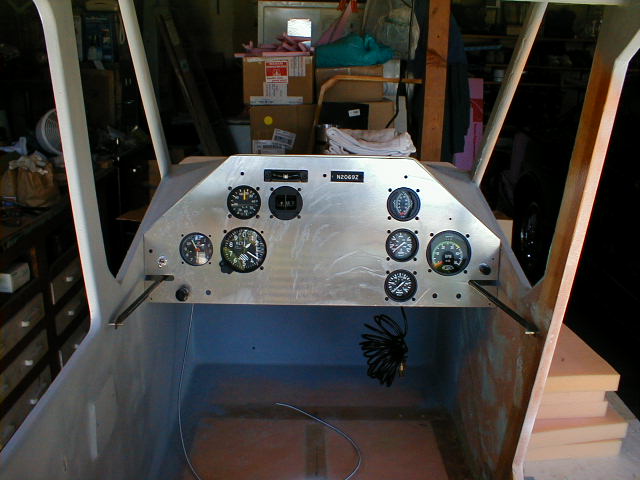 Here's the panel and instruments mocked-up in the cabin.
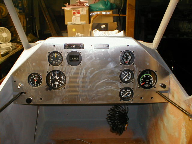 A bit closer view of the panel and instruments. Remember, the blank space in the center area of the panel will be for handheld COM and GPS units.
 And here's the panel showing my first attempt at black wrinkle paint. First I primed it, then followed the directions on the can (Tempo products). Didn't turn out too bad, except for a sag and run here and there. I'm not going to sand it off and do it again! The back side was painted using white primer, for better contrast when working back behind the panel.
Now I'm ready to work on the cabin air and heat controls, pitot and static tubing, wiring, etc.
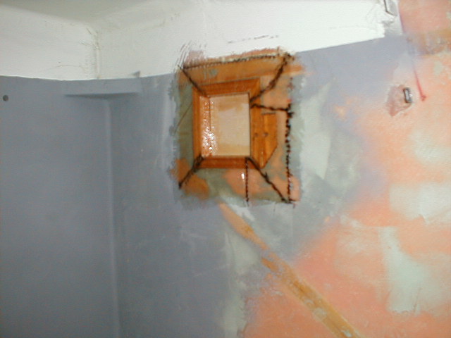 It hurt, but I had to do it. Cut a hole in the side of my cabin, then fitted and glassed in a small wood frame to mount the cabin air intake on. It was all pre-measured and fitted, and tested to make sure the air intake door worked before I glassed it in. I have since cut the hole on the outer skin.
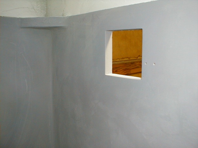 Here's how the hole finished up after sanding, filling, priming, and cutting out the hole.
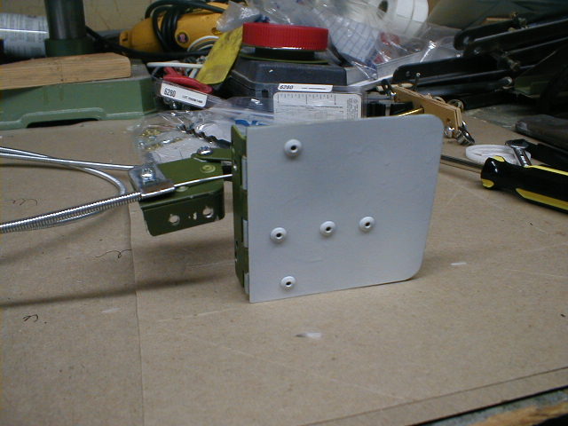
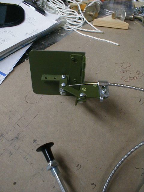 Here's the cabin air intake door assembly, made of bits and pieces of aluminum and a hinge. Automotive choke cable controls it from the panel. It's hard to see, but the mounting bracket for the control cable is actually 2 layers of metal, with the top layer cut back where the pivot link mounts to it, forming a positive stop so the link can't pivot "over center".
 Here's another view of the air door, from outside. Very similar to the door on a Super Cub.
Return to My Flying Squirrel Home Page