Corvair Engine
CORVAIR ENGINE
revised January 24, 2003 (added link to the Corvair College)
Click here to read about the Alamo City Corvair College
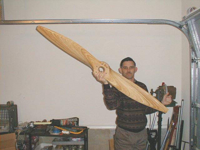
Here's what a Tennessee Props 62x34, left-hand, through-bored (for safety shaft) propeller looks like. SAE#1 bolt pattern for the William Wynne prop hub. The tips have since been painted Daytona Yellow.
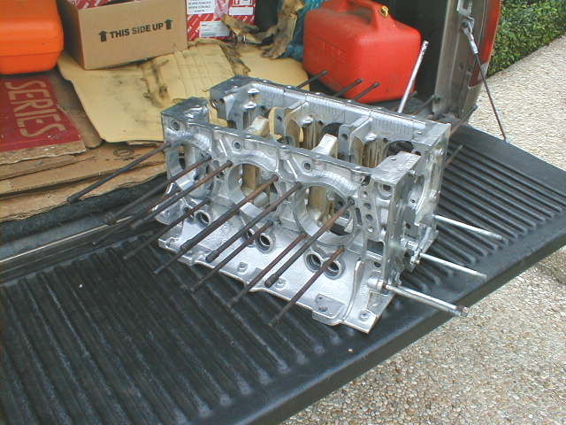
Clean cases, finally! The cases had been in a box since I first got the engine a few years ago, and I knew it would be a messy project getting them cleaned up, so I put that chore off for as long as I could and just let the sludge and road grime protect the cases from corrosion in storage. Taking them to Groff's Machine Shop and running them through Ronnie's "cold tank" got all the crud and grime off, got the old gaskets and gunk off, and here's the result. Still need to degrease the studs and chase the threads on 'em, then repaint the cases and studs, but these things are now clean enough to eat off of (or take inside the house without fear of bad things happening) ;o) The discerning 'Vairhead will note that one stud (top row, second from left, the one with a nut on it) turned out when the engine was disassembled, and will need to be Locktited back in place. All the others were kept from turning and are A-OK.
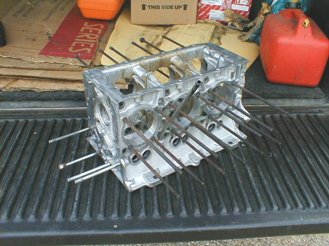
Here's a shot of the other side of the cases, showing the dipstick tube side. This is an RH engine, supposedly out of a '65 with automatic transmission, but who really knows? Visible on the inside walls of the case is a slight tan stain that the cleaning chemicals just couldn't remove, and I'll live with it. Old varnish and sludge is pretty strong stuff when it's sat there for 30 years after getting baked on for 150,000 miles or so.
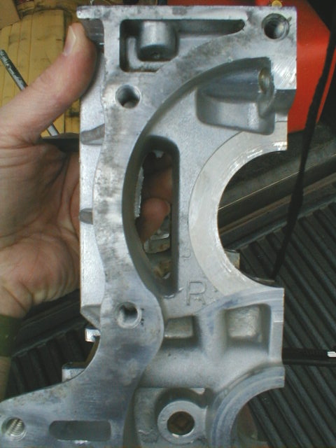 This is the sort of stuff to look for when cleaning up your cases... casting flash. In the side of the semi-circular opening you can see some flash. I easily popped off a nice big hunk of this with my finger, and this was just one of many spots inside the engine that has flash that needs to be cleaned up. It's bewildering how little attention the factory paid to cleaning up the castings in the Corvair, but perhaps it says a lot about how robust and simple the engine is. We must take greater care in assembling our aero conversions, but it's still not brain surgery... just a little common sense and attention to detail. And once we get the engine done, we hope never again to have to see the inside of our CorvAIRCRAFT powerplants in our lifetimes (or TBO, whenever that is!)
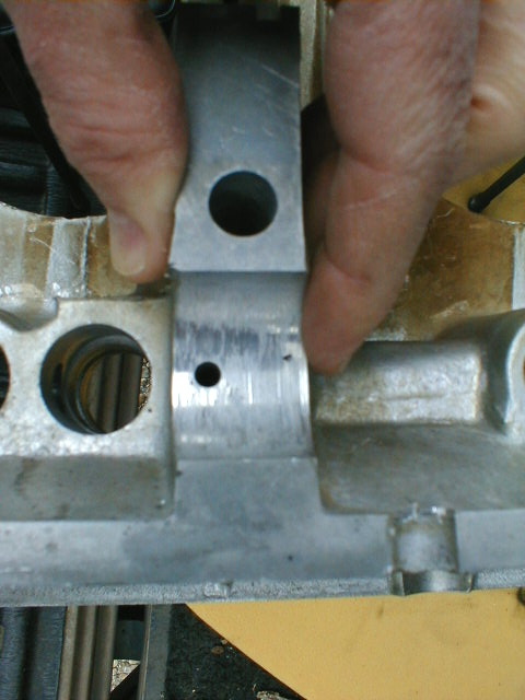 Here's one of the few places that I worry about on the engine... the cam journals. Since the Corvair cam rides directly in journals in the case (no bearing inserts), damaged cam journals usually mean scrapping the cases. Mine cleaned up very nicely, showed a smidgen of roughness/galling that should polish out OK, but right by my finger a little pit is visible (black spot). No way to get rid of this, but it should be OK.
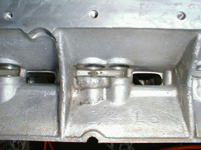 Hmmm... what's this? Could it be that this engine had a problem sometime in its past, something that required welding right there at the lifter guide? Looks like 'heliarc' to me... but the lifter guide bores are nice and everything looks hunky-dory. What stories these engines could tell, if we knew their histories-!
February 2, 2002
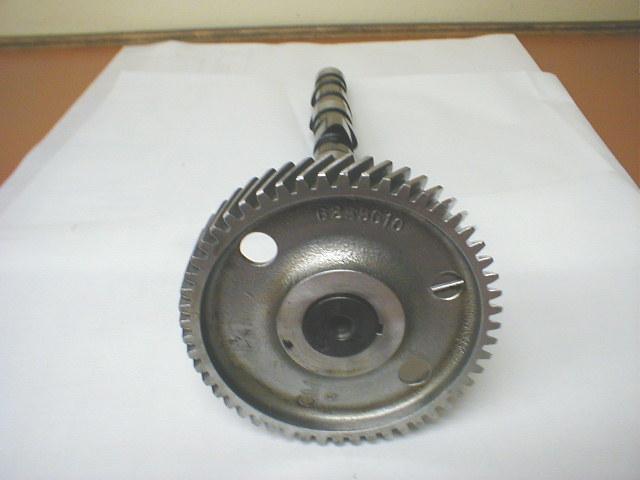
Here is the gear end of my cam as it looked after receiving it from Delta Camshafts . Delta reground it to their DEL-319 profile, very similar to the OT-10 grind offered by Clark's Corvair. Cost including shipping, checking out, cleaning, regrinding: less than $70. The cam looks like new (to me); light coating of oil is the drips that are visible.
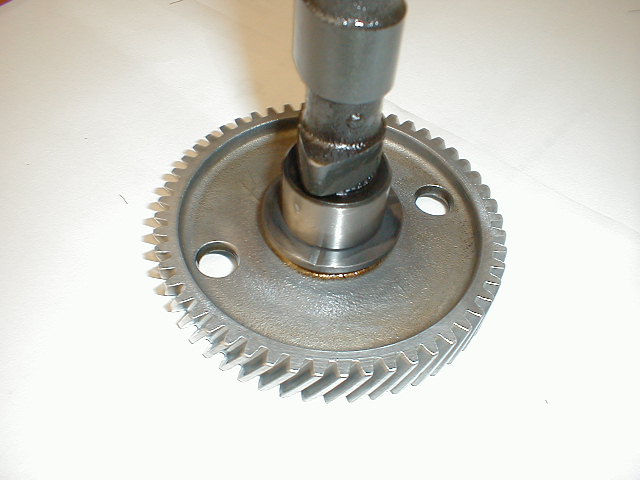
Close-up of the backside of the cam gear. They cleaned the cam up extremely well, as well as checking all parts of it for out-of-spec prior to doing the regrind. However... both William Wynne and Lon Wall of Corvair Underground recommend that the cam gear be replaced when doing a complete overhaul, so this cam gear is history. When it gets replaced, the washer and key also get changed out. I got Corvair Underground to replace the gear with a new one and we're good to go.
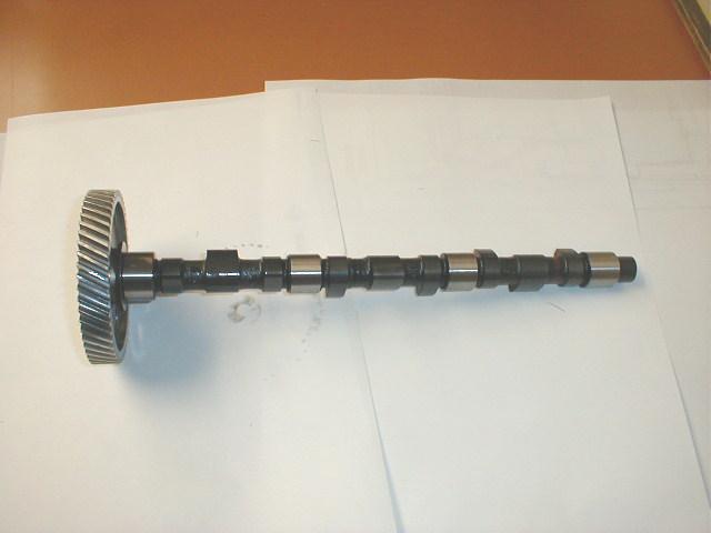 And here it is overall. They give the cam a nice finish, and polish the bearing/journal surfaces nicely. When the cam was sent off, it had very noticeable tracking, pitting, offset wear, and other bad stuff on many of the cam lobes and here and there on the bearing surfaces. All gone (lobes were all repaired, built-up, and reground).
January 19, 2002:
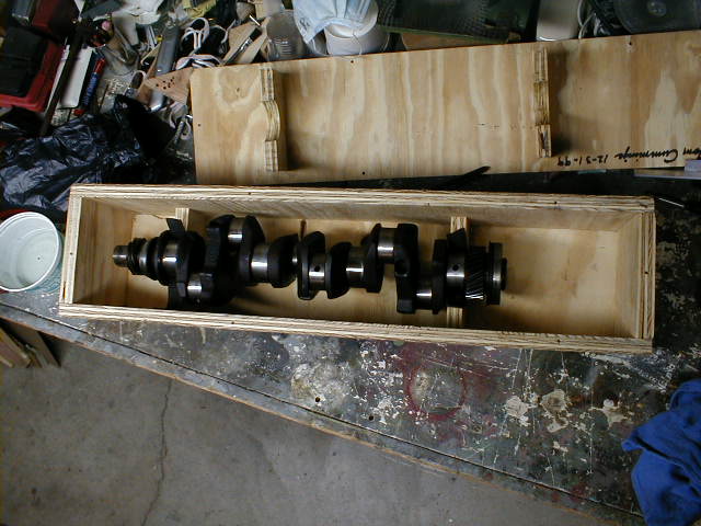
Here is my old crank as it came out of the engine, prepared for shipping to William Wynne for conversion into a CorvAIRCRAFT crank! After receiving it, he threaded and fitted it with a safety shaft and new studs, all of which will secure the prop hub to the end of the crank. I also have a partially-completed prop hub, made by Joa Harrison according to William's drawing. The plywood shipping box was fabricated by William for use by 'Vairheads in shipping cranks to him and back. Cranks should be checked for damage and magnafluxed before spending any time or money using them in a conversion. I had Ronnie Groff at Groff's Machine Shop magnaflux mine, and also had him lightly chamfer the oil holes and polish the journals while he had the crank.
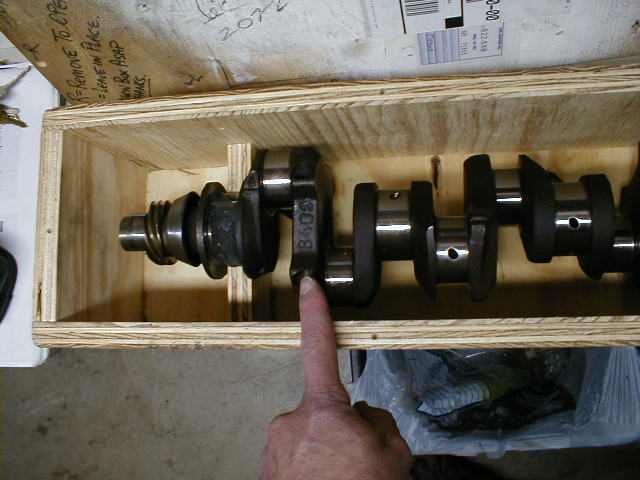 Here's the crank you want: the 8409. Although all Corvair cranks are forged, the early ones are different (don't have clearancing that the later ones do) and the ones off the high-output or turbo engines have a nitriding. Visit the CorvAIRCRAFT FAQ site for a complete detailing of the differences if you want, but just make it simple on yourself and stick with the 8409 in a 164 CID, 110 HP engine!
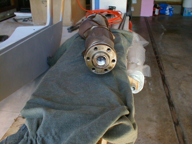 This is the internal threading in the crank nose, for the safety shaft (obviously not yet cleaned up). The flange (with 6 holes) can be pressed off and the crank cross-drilled for a pin to lock the safety shaft in place, then the flange pressed back on to keep the pin from coming out. Or, as in my case, the flange is kept in place with the factory fit (very tight) and the cross-pin dispensed with. The six holes in the flange are an unusual thread pattern, so special hybrid "magic" studs are used to provide a more standard thread pattern to bolt the prop hub to the crank flange. Then the safety shaft locks the hub to the crank and flange with a nut. It's definitely "belt-and-suspenders". There is now a simpler, easier, stronger way to secure the flange without threading the nose of the crank or involving the safety shaft at all: a snap ring. A groove is cut into the crank just ahead of the face of the flange and a snap ring installed to hold it in place should the tight press-fit ever let go. This will not prevent the flange from rotating on the nose of the crank, but it will prevent it from departing entirely... along with your prop.
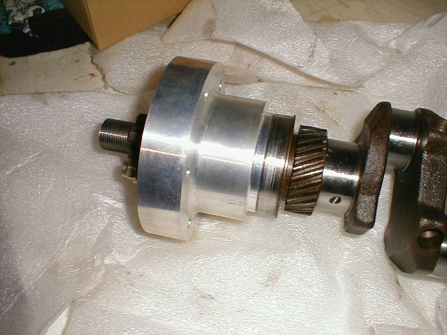 Here is the prop hub mated to the crank. Most installations will include either a flex plate ("flywheel", with gear teeth for starter, when using a front-mounted starter), a spacer puck, a pulley (if driving a dynamo or alternator at this end), or something else in between the crank flange and the hub. In this photo, they are butted together with nothing in between, so the safety shaft and studs protrude more than necessary out the face of the hub (see next photos...)
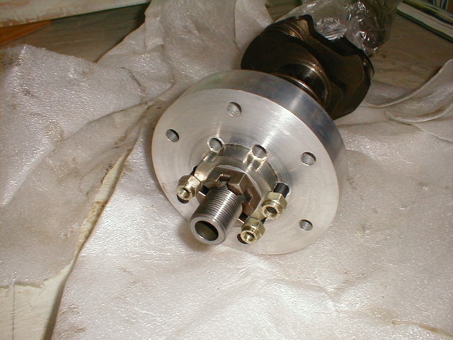 Here's the face of the hub, showing the "magic studs" that secure the prop hub to the crank flange, and the threaded safety shaft that double-secures the whole works together. You can see the excess length of the studs and safety shaft since I don't have a spacer puck installed. My safety shaft is not yet drilled for its cotter pin; that happens after final fitting of everything.
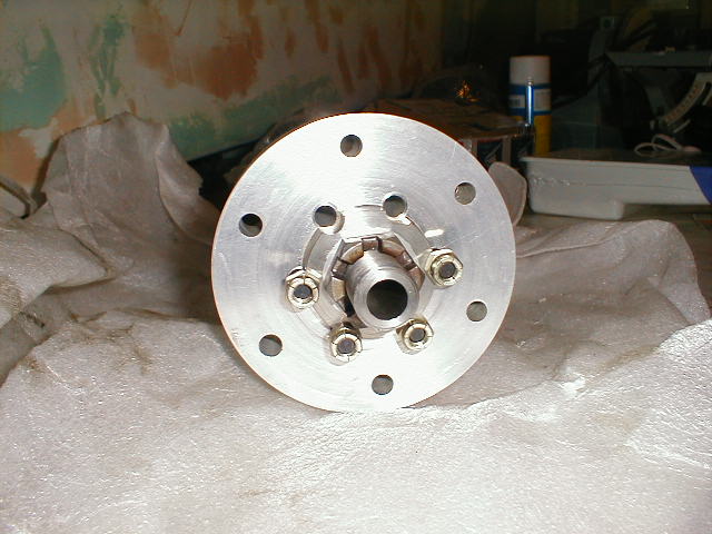 Evident here is the fact that I haven't yet had the stud holes counterbored to allow the nuts to run down where they seat... there isn't even clearance for the nuts, much less a socket or wrench to tighten them. Two of my six studs were on loan to Mark Langford when this photo was taken.
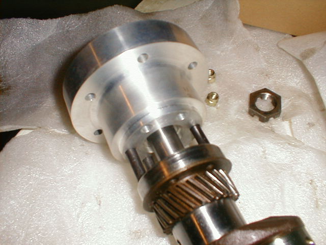 An out-of-focus shot showing the prop hub pulled away from the crank flange to show machining on the aft face of the hub. My hub is not fitted with drive lugs, but will be bolted straight through the prop and hub with AN6 bolts. Depending on your application (particularly the 3100cc "Big Boy" conversion), drive lugs should be used.
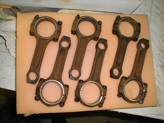 Here are the rods that came out of my engine, cleaned up and ready to send off to William Wynne as cores for a set of reconditioned rods. I haven't yet popped out the old bearings on all of them, so some have part or all of them still in the big ends. After I got the reconditioned rods, they were sent off to Corvair Underground to have the new .020 overbore forged pistons and pins installed. Some folks also weigh and balance the rods, although many sets are already fairly well balanced in weight between them and ready to go as-is. I didn't bother with weighing and balancing. This set out of my engine has numbers stamped on them, 1 through 6. Nice.
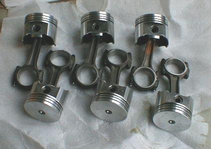 And here are the completed piston/rod assemblies (without rings, yet). These have ARP rod bolts, which William Wynne recommends as a must. Otherwise, these same components are what are used in the turbo Corvair that is rated at 180HP, and in racing Corvairs that go up to several hundred HP, so they will certainly be comfy at 100HP in my engine.
Return to Oscar Zuniga's M-19 Project